HFBR-0562 Avago Technologies US Inc., HFBR-0562 Datasheet - Page 11
HFBR-0562
Manufacturer Part Number
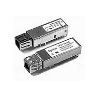
HFBR-0562
Description
Fiber Optics, Evaluation Kit
Manufacturer
Avago Technologies US Inc.
Specifications of HFBR-0562
Silicon Manufacturer
Avago
Silicon Core Number
HFBR-591xE, HFCT-591xE
Kit Application Type
Communication & Networking
Application Sub Type
MT-RJ Gigabit Ethernet Transceiver
Main Purpose
Interface, Ethernet
Embedded
No
Utilized Ic / Part
HFCT-591xE, HFBR-591xE
Primary Attributes
MT-RJ 1.25Gb Multimode Applications
Secondary Attributes
MT-RJ Fiber Connector Interface
Description/function
Fiber Optic Kit
Lead Free Status / RoHS Status
Lead free / RoHS Compliant
For Use With/related Products
HFBR-591x
Lead Free Status / RoHS Status
Lead free / RoHS Compliant, Contains lead / RoHS non-compliant


Figure 2. Pin Out
Table 1. Pin Out Table
Note:
1.
Two Mounting
Studs
Four Package
Grounding Tabs
Pin
10
3
4
8
1
2
5
6
7
9
The Transmitter and Receiver V
Symbol
V
V
TDis
RD+
TD+
V
V
RD-
TD-
SD
EER
EET
CCR
CCT
1
1
RECEIVER SIGNAL GROUND
RECEIVER POWER SUPPLY
RECEIVER DATA OUT BAR
The mounting studs are provided for transceiver mechanical attachment to the circuit
equipment chassis ground.
Note :-
Connect to signal ground.
Receiver Signal Ground
Directly connect this pin to receiver signal ground plane.
Receiver Power Supply
Signal Detect
Normal operation: Logic “1” Output
Fault Condition: Logic “0” Output
Received Data Out Bar
No internal terminations provided.
Received Data Out
No internal terminations provided.
Transmitter Power Supply
Transmitter Signal Ground
Transmitter Disable:
Normal Operation: Logic "0" - Laser On or Open Circuit
Transmit Disabled: Logic "1" - Laser Off
Transmitter Data In
Transmitter Data In Bar
(See TD+ pin for terminaton details)
board, they may also provide an optional connection of the transceiver to the
An internal 50R termination consisting of 100R across TD+ and TD- will be provided
RECEIVER DATA OUT
Grounding Tabs
SIGNAL DETECT
Package
EE
The holes in the circuit board must be tied to chassis ground.
connections are commoned within the module.
f
f
f
f
f
RX
1
2
3
4
5
View
Top
Functional Description
10
TX
9
8
7
6
f
f
f
f
f
TRANSMITTER DATA IN BAR
TRANSMITTER DATA IN
TRANSMITTER DISABLE
TRANSMITTER SIGNAL GROUND
TRANSMITTER POWER SUPPLY
Mounting Studs/
Solder Posts
11
Related parts for HFBR-0562
Image
Part Number
Description
Manufacturer
Datasheet
Request
R

Part Number:
Description:
Fiber Optic Transmitters, Receivers, Transceivers 1300nm 155MBd 16-pin DIP ST Rx
Manufacturer:
Avago Technologies US Inc.

Part Number:
Description:
FIBER OPTIC TX 125 MBD 650N
Manufacturer:
Avago Technologies US Inc.
Datasheet:

Part Number:
Description:
Fiber Optic Evaluation Kit
Manufacturer:
Avago Technologies US Inc.
Datasheet:

Part Number:
Description:
RECEIVER FIBER OPTIC ST 266MBD
Manufacturer:
Avago Technologies US Inc.
Datasheet:

Part Number:
Description:
RCVR OPT HI SPEED VERS LINK HORZ
Manufacturer:
Avago Technologies US Inc.
Datasheet:

Part Number:
Description:
RCVR OPT HI SPEED VERS LINK VERT
Manufacturer:
Avago Technologies US Inc.
Datasheet:

Part Number:
Description:
TXRX OPTICAL 850NM VCSEL MT-RJ
Manufacturer:
Avago Technologies US Inc.
Datasheet:

Part Number:
Description:
TXRX MM SFP LC CONN BAIL DELATCH
Manufacturer:
Avago Technologies US Inc.
Datasheet:

Part Number:
Description:
TXRX MMF SFP GBE/FC BAIL DELATCH
Manufacturer:
Avago Technologies US Inc.
Datasheet:

Part Number:
Description:
XMITTER FIBER OPTIC 266MBD ST
Manufacturer:
Avago Technologies US Inc.
Datasheet:

Part Number:
Description:
OPTOCOUPLER GATE DRV 2A 16-SOIC
Manufacturer:
Avago Technologies US Inc.
Datasheet:
Part Number:
Description:
OPTOCOUPLER 2CH 2.5A 16-SOIC
Manufacturer:
Avago Technologies US Inc.
Datasheet:

Part Number:
Description:
OPTOCOUPLER GATE DRV 0.4A 16SOIC
Manufacturer:
Avago Technologies US Inc.
Datasheet:

Part Number:
Description:
OPTOCOUPLER 2.0A 250KHZ 8-DIP
Manufacturer:
Avago Technologies US Inc.
Datasheet:

Part Number:
Description:
OPTOCOUPLER 2.0A 250KHZ GW 8-SMD
Manufacturer:
Avago Technologies US Inc.
Datasheet: