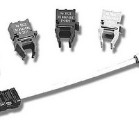
HFBR-0572 Avago Technologies US Inc., HFBR-0572 Datasheet - Page 4

HFBR-0572
Manufacturer Part Number
HFBR-0572
Description
Fiber Optics, Evaluation Kit
Manufacturer
Avago Technologies US Inc.
Datasheet
1.HFBR-0572.pdf
(8 pages)
Specifications of HFBR-0572
Silicon Core Number
HFBR-5921L, HFBR-5923L
Kit Contents
Evaluation PC Board, Associated Technical Literature
Features
Applicable For Evaluating 2x5 Or 2x6 Pin Small Form Factor Transceivers
Main Purpose
Interface, Fiber Optics
Embedded
No
Utilized Ic / Part
HFBR-5921L, HFBR-5923L
Primary Attributes
SFP PTH Multimode Fibre Channel Applications
Secondary Attributes
Small Form Factor Pluggable (SFP)
Description/function
Fiber Optic Kit
Lead Free Status / RoHS Status
Lead free / RoHS Compliant
For Use With/related Products
HFBR-5921L, HFBR-5923L
Lead Free Status / RoHS Status
Lead free / RoHS Compliant, Contains lead / RoHS non-compliant
III. Electro-Optical Test Configuration(s)
The two basic test configurations for evaluating the 10-
or 12-pin SFFs are shown in Figure 2 (transmitter) and
Figure 3 (receiver or loopback). These test configura-
tions use one evaluation board and the test instruments
from the equipment list, such as a Bit-Error-Ratio Tester
(BERT) and a Digital Communication Analyzer (DCA).
General considerations from the test configuration fol-
low, but more specific details on SFF transceiver testing
can be found in the documents listed in the reference
section of this document.
Transmitter Configuration:
This configuration is shown in Figure 2. The SFF’s optical
characteristics can be tested including the eye diagram,
jitter, and rise/fall time. A representative eye diagram
for an SFF is shown in Figure 4. In this configuration, the
receiver is not used, however it is recommended that
RD- and RD+ be terminated by 50 W matched loads. It
is also recommended that low loss, low dispersion, and
equal length RF cables be used to connect TD+/- to the
test equipment.
Figure 2. Recommended Transmitter Test Configuration
Figure 3. Recommended Receiver Configuration
4
Error Detector
Error Detector
Generator
Generator
Clock Source
Clock Source
Bit-Error Rate Tester
Bit-Error Rate Tester
Pattern
Pattern
Data Pattern Clk In
Data Pattern Clk In
Mainframe
Mainframe
Display
Display
Trigger Out
Trigger Out
Data Out
Data Out
Data Out
Data Out
Data In
Clk Out
Clk Out
Data In
Clk Out
Clk Out
Clk In
Clk In
2.125 Gb/s or
2.125 Gb/s or
1.0625 Gb/s
1.0625 Gb/s
+3.3 V
+3.3 V
Gnd
Gnd
PRBS 2
PRBS 2
VccT
VeeT
VccT
VeeT
7
7
-1
-1
TD +
TD +
50 Ω
RD +
load
RD +
Evaluation Board
Evaluation Board
BER = 1x10
BER = 1x10
TD -
TD -
50 Ω
load
RD -
RD -
-12
-12
VeeR VccR
VeeR VccR
Receiver Configuration
This configuration is shown in Figure 3. The SFF’s electri-
cal characteristics can be tested including the receiver
electrical eye diagram, jitter, and rise/fall time. A repre-
sentative eye diagram for an SFF is shown in Figure 5.
Results
The following example measurements were made
using the configurations illustrated in Figures 2 and 3
respectively.
Gnd
Gnd
Trans-
Trans-
ceiver
ceiver
All Inputs are
50 Ω
to Ground
All Inputs are
50 Ω
to Ground
SW1
SW1
+3.3 V
+3.3 V
TX Dis
TX Dis
T
R
T
R
Tx Eye
Configuration
Fiber-Optic
Fiber-Optic
Optional
Optional
Attenuator
Attenuator
Loop-back link
Configuration
Pads
6 dB
Pads
6 dB
6 dB
Pad
Data (optical channel)
Data (electrical channel)
Data (optical channel)
Data (electrical channel)
Trigger
Trigger
O/E Plug In
O/E Plug In
86100 A
86100 A
DCA
DCA


