AMICUS18-COMPANION-SHIELD AMICUS, AMICUS18-COMPANION-SHIELD Datasheet
AMICUS18-COMPANION-SHIELD
Specifications of AMICUS18-COMPANION-SHIELD


Related parts for AMICUS18-COMPANION-SHIELD


AMICUS18-COMPANION-SHIELD Summary of contents
Page 1
... Amicus18 Companion Shield ...
Page 2
... Amicus18 Companion Shield Amicus18 Companion Shield ...................................................................................2 Companion Shield Options ............................................................................................3 Building the Companion Shield ......................................................................................4 First Program..................................................................................................................................... 7 2 LED Flasher ...................................................................................................................................11 4 LED Sequencer...............................................................................................................................13 8 LED Sequencer...............................................................................................................................16 Traffic Light Sequencer......................................................................................................................19 Sensing the Outside World.......................................................................................... 21 Switch Input (Pulled-Up)....................................................................................................................21 Switch Input (Pulled-Down) ...............................................................................................................24 Switch Debounce ..............................................................................................................................27 Analogue Meets Digital ............................................................................................... 30 Light Level Switch (Cockroach Mode) ...
Page 3
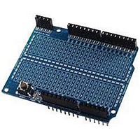
... Amicus18 Companion Shield Amicus18 Companion Shield A shield is a PCB that fits over the Amicus18 board and provides extra functionality, such as Ethernet, Motor control, LCD, Smartcard, GPS, GSM etc… All Arduino shields will physically fit on the Amicus18, however, Arduino source code is not compatible with Amicus18, as they differ in two very crucial aspects. First, the Amicus uses a Microchip PICmicro for it’ ...
Page 4
... Amicus18 Companion Shield Companion Shield Options The companion shield is available as a blank PCB or ready built. However, there are two flavours of the ready built boards, one with header sockets, and one with header pins. It all depends on what you need to do with the companion shield. The illustrations below show the various flavours: ...
Page 5
... The two flavours of the shield allow the boards to be stackable or at the top of the stack: The illustration above shows the Amicus18 board at the bottom of the stack, then a socketed shield, then a pinned shield. A pinned shield could carry an LCD or other user interfacing device that would not suit being stacked between other PCBs ...
Page 6
... Amicus18 Companion Shield Next solder on the resistor R6 which is a 1KΩ 1% 0805 casing type: Next to solder is the power indicator LED, this is a red type 0805 casing, but any colour will do. Note that resistor R6 is not required if the LED is omitted: Take note of the orientation of the LED, make sure the Anode is located as in the above diagram. Re- versing the LED won’ ...
Page 7
... Amicus18 Companion Shield The next component is the reset button, this is a standard PCB push to make type: Then place either the header pins or the header sockets as the earlier diagram illustrate. These are standard 2.54 (0.1”) spacing Single Inline types (SIL). You will require 5 of these: ...
Page 8
... RB1, and the Anode connected to RB0. The Cathode is identified by being the shorter of the two wires, and also the body of the LED has a flattened side. Connect the USB cable to the Amicus18 board, and make sure its red Power LED is illuminated. Press Compile and Program the button on the toolbar, or press F10 ...
Page 9
... Once the program is typed into the IDE, press the toolbar’s code and place it into the Amicus18’s microcontroller. As long as no typing errors have been made, the LED will then begin to flash. If any errors are found the offending line will be highlighted and an error message will be displayed on the bottom of the IDE ...
Page 10
... Amicus18 Companion Shield How to choose the resistor value A resistor is a device designed to cause resistance to an electric current and therefore cause a drop in voltage across its terminals. If you imagine a resistor to be like a water pipe that is a lot thinner than the pipe connected to it. As the water (the electric current) comes into the resistor, the pipe gets thin- ner and the current coming out of the other end is therefore reduced ...
Page 11
... Amicus18 Companion Shield We need a 47Ω resistor look at the colour table we see that we need 4 in the first band, which is Yellow, followed the next band which is Violet and we then need to multiply this by 100 rd which is Black in the 3 band. The final band is irrelevant for our purposes as this is the tolerance. Our resistor has a gold band and therefore has a tolerance of ± ...
Page 12
... Amicus18 Companion Shield 2 LED Flasher Adding a second LED is simple, and the code for driving them is not too difficult either: Crownhill AssociatesLimited 2009 - All Rights Reserved Version 1.0 11 06-10-2009 ...
Page 13
... Amicus18 Companion Shield The circuit for the two LED flasher layout is shown below: The code for driving the LEDs is shown below: ' Flash 2 LEDs connected to RB2 and RB3 Symbol LED1 = RB2 Symbol LED2 = RB3 While High LED1 DelayMS 500 Low LED1 High LED2 ...
Page 14
... Amicus18 Companion Shield 4 LED Sequencer Adding, and using, extra LEDs is also very simple, as illustrated below: Crownhill AssociatesLimited 2009 - All Rights Reserved Version 1.0 13 06-10-2009 ...
Page 15
... The two extra LEDs are connected to RB0 and RB1 of PortB, as the circuit shows below: A suitable program for the 4 LED sequencer is shown below: ' Illuminate 4 LEDs attached to PortB in sequence ' Make sure the Amicus18 board’s jumper Q3 is set to the RB1 position ' Low PORTB ...
Page 16
... There are many variations of the programs that can be used with the four LED circuit. The program be- low sequences the LED’s up then down the line. ' Illuminate 4 LEDs attached to PortB in sequence ' Make sure the Amicus18 board’s jumper Q3 is set to the RB1 position ' Dim bPortShadow As Byte ...
Page 17
... A more sophisticated layout is shown below, in which eight LEDs are used. Notice how the use of differ- ent colour LEDs adds a new twist: A top down view of the above layout is shown below for extra clarity: Note. Make sure the Amicus18’s Crownhill AssociatesLimited 2009 - All Rights Reserved Version 1.0 Q3 jumper is set to the RB1 position ...
Page 18
... Power GND A suitable program for the 8 LED sequencer is shown below: ' Illuminate 8 LEDs attached to PortB in sequence ' Using discrete commands ' Make sure the Amicus18 board’s jumper Q3 is set to the RB1 position ' Low PORTB ' Make PortB output low (Extinguish all the LEDs) While ...
Page 19
... There are many variations of the programs that can be used with the eight LED circuit. The program below sequences the LED’s up then down the line. ' Illuminate 8 LEDs attached to PortB in sequence ' Make sure the Amicus18 board’s jumper Q3 is set to the RB1 position ' Dim bPortShadow As Byte ...
Page 20
... Amicus18 Companion Shield Traffic Light Sequencer Using an adaptation of the 8 multi-coloured LED layout, we can create the sequence for a UK traffic light. The layout is shown below, notice that the only difference is the removal of four LEDs and four resistors: Crownhill AssociatesLimited 2009 - All Rights Reserved Version 1 ...
Page 21
... Wait for the appropriate length of time ' Extinguish the Green LED ' Illuminate the Amber LED ' Wait for the appropriate length of time ' Extinguish the Amber LED ' Do it forever button or press F10 to compile the code and load it into the Amicus18’ Ω LED 06-10-2009 ...
Page 22
... Amicus18 Companion Shield Sensing the Outside World Interacting with the outside world is always desirable when using a microcontroller, whether it’s choos- ing a drink in a vending machine or deciding which way a pacman will move. The easiest method of out- side influence is through the use of a switch or button. ...
Page 23
... Click the toolbar icon Amicus18’s microcontroller. Open the Serial Terminal by clicking on the toolbar, and open a connection to the Amicus18. Use the default baud of 9600. The serial terminal’s window should show the text “Button = 1”. This is dis- playing the state of the pin where the button is attached. Press the button and the test will change to “ ...
Page 24
... Amicus18 Companion Shield Notice how the state of the pin is 0 when the button is pressed. This is because the weak pull-up resis- tor (22K ) holds the pin to 3.3 Volts when it’s not being operated, and the button pulls the pin to Ω ground when it’s operated. ...
Page 25
... Amicus18 Companion Shield Switch Input (Pulled-Down) The layout below shows a pull-down resistance: Crownhill AssociatesLimited 2009 - All Rights Reserved Version 1.0 24 06-10-2009 ...
Page 26
... Click the toolbar icon Amicus18’s microcontroller. Open the Serial Terminal by clicking on the toolbar, and open a connection to the Amicus18. Use the default baud of 9600. The serial terminal’s window should show the text “Button = 0”. This is dis- playing the state of the pin where the button is attached. Press the button and the test will change to “ ...
Page 27
... Amicus18 Companion Shield Notice how the state of the pin is 1 when the button is pressed. This is because the weak pull-up resis- tor (22K ) holds the pin to ground when it’s not being operated, and the button pulls the pin to 3.3 Ω Volts when it’s operated. This is the exact opposite of using a pull-up resistor. ...
Page 28
... This can cause a single switch push to be detected as several distinct switch pushes by the fast microcontroller used in the Amicus18 board, especially with an edge-sensitive input. Think of advancing the TV channel, but instead of getting the next channel, the selection skips ahead two or three. ...
Page 29
... Amicus18 Companion Shield The same layout as the pulled-up switch demonstration can be used: The circuit for the debounced pulled-up switch input is shown below: Crownhill AssociatesLimited 2009 - All Rights Reserved Version 1.0 PortB RB7 Power Push RB6 Button RB5 Vin RB4 GND RB3 ...
Page 30
... Amicus18 Companion Shield In order to detect and debounce a switch that is pulled down to ground through a resistor, the following code can be used. It’s essentially the same program as the pulled up version, but references to 0 now reference 1, and vice-versa: ' Debounce a switch input (Pulled-Down) ' The LED will toggle On and Off whenever the switch is pressed ...
Page 31
... This is where an Analogue to Digital Converter (ADC) comes into it’s own. An ADC samples the incoming voltage and converts binary representation. The Amicus18 has nine ADC inputs, each capable of producing a 10-bit sample (0 to 1023). The ADC can measure re- sistance, current, sound, in fact anything that has a voltage ...
Page 32
... Dec ADC_Input, 13 DelayMS 500 Wend Once the program is compiled and loaded into the Amicus18 board by clicking on the toolbar and Program or pressing F10, open the serial terminal and connect to the Amicus18 board’s com port: Pot Fully Clockwise (0 Volts) Pot Mid Way (Approx 1.6 Volts) Pot Fully Anti-Clockwise (3 ...
Page 33
... Amicus18 Companion Shield Light Level Switch (Cockroach Mode) We can use the ADC for a more practical example now that we know it works. We’ll use an LDR (Light Dependant Resistor) as the input to the ADC, and turn on an LED when the light level drops beyond a certain level. ...
Page 34
... Amicus18 Companion Shield Don’t worry if the LDR you use doesn’t look like the one used in the layout as LDRs come in all shapes and sizes, but they all perform the same task. However, their light level resistance may vary. But again, this doesn’ ...
Page 35
... LDR_Value = ReadADC(0) HRSOut Dec LDR_Value, 13 DelayMS 500 Wend Once the code is compiled and loaded into the Amicus18, open the serial teminal: Light Level Dropped Here Light Level Increased Here As can be seen from the above screenshot, ambient light levels give an approximate value of 315, so anything above this value will indicate a light level decrease. However, we don’ ...
Page 36
... Amicus18 Companion Shield Light Level Switch (Moth Mode) The same circuit and layout is used for the opposite reaction to light levels. The code below will illumi- nate the LED when light levels increase, just like a moth to a flame. ' Illuminate an LED when an LDR connected to AN0 sees light ...
Page 37
... Amicus18 Companion Shield Temperature Sensor One of the simplest, and least expensive, temperature sensors is a thermistor. This is a special type of resistor that alters it’s resistance based upon it’s temperature. There are generally two types of thermis- tor; an NTC type (Negative Temparature Coefficient), whose resistance drops as the temparature in- creases, and a PTC type (Positive Temparature Coefficient), whose resistance increases as the tempara- ture increases. For this demonstration, we’ ...
Page 38
... DelayMS 500 Wend Once the program has been loaded into the Amicus18 board, open the serial terminal and connect to the Amicus18’s com port: The display shows the decrease in voltage with the increase in temperature when a finger covers the thermistor, and is then removed. As can be seen, a thermistor is quite sensitive. ...
Page 39
... High LED Else Low LED EndIf Wend Once the program is compiled and loaded into the Amicus18 board using the toolbar gram F10 or pressing , placing a finger over the thermistor, thus increasing the temperature, will illumi- nate the LED. To adjust the threshold of the temperature trigger, alter the value within the code line: “ ...
Page 40
... High LED Else Low LED EndIf Wend Once the program is compiled and loaded into the Amicus18 board using the toolbar gram F10 or pressing , blowing over the thermistor, thus decreasing the temperature, will illuminate the LED. To adjust the threshold of the temperature trigger, alter the value within the code line: “If ThermistorIn > ...
Page 41
... Amicus18 Companion Shield Thermostat (increase and decrease of temperature) The layout and code below allows the demonstration of high, normal, and low temperature changes. Both LEDs will be extinguished when the temperature is normal, the Red LED will illuminate when the temperature rises above a pre-determined value, and the Green LED will illuminate when the tempera- ...
Page 42
... Amicus18 Companion Shield The circuit for the thermistat layout is shown below: PortA AN4/AN5 AN3/RA3 AN2/RA2 AN1/RA1 AN0/RA0 Power The code for the two LED thermostat is shown below: ' Illuminate a Red LED when the temperature increases ' Illuminate a Green LED when the temperature decreases ...
Page 43
... Pulse Width Modulation (PWM) Pulse Width Modulation fakes a voltage by producing a series of pulses at regular intervals, and varying the width of the pulses. The resulting average voltage is the result of the pulse widths. The Amicus18’s microcontroller can produce a high voltage of 3.3 Volts and low of 0 Volts. ...
Page 44
... PWM macro’s operate at a frequency of 62.5KHz (62,500 Hertz), and the 8-bit PWM macros operate at a frequency of 125KHz (125,000 Hertz), but only if the Amicus18 board is using it’s default oscillator speed of 64MHz. If the crystal is replaced with another value type, these frequencies will section 16 change ...
Page 45
... The circuit for the PWM1 layout is shown below: The PWM peripherals operate in the background, which means that once a PWM duty cycle is set, it does not block any other instructions from occurring. Type in the following code and program it into the Amicus18 board by clicking on the toolbar and Program , or pressing F10: Include " ...
Page 46
... Amicus18 Companion Shield Channel 2 PWM As has been mentioned, the Amicus18 has two hardware PWM channels, each can work independently of each other when adjusting the duty cycle, but share a common operating frequency and resolution. This is because they both operate from the microcontroller’s Timer 2 module. ...
Page 47
... Amicus18 Companion Shield Type in the following code and program it into the Amicus18 board by clicking on the toolbar and Program , or pressing F10: Include "Hpwm10.inc" WriteAnalog2(512) The LED will now be glowing, but not at full brightness. What’s happening is that channel 2 of the PWM has been instructed to set the duty cycle to 50%, which is half the full range of 1023, which is 512. Try different values within the braces of the WriteAnalog2 command and see what it does to the LED’ ...
Page 48
... Amicus18 Companion Shield Two channels of PWM simultaneously (Pulsing Light) The layout below demonstrates both PWM channels operating simultaneously: Crownhill AssociatesLimited 2009 - All Rights Reserved Version 1.0 47 06-10-2009 ...
Page 49
... Amicus18 Companion Shield The circuit for the 2 PWMs layout is shown below: The capacitors normally associated with PWM output have been dispensed with because the operating frequency of the PWM channels is so high (62.5KHz) that no noticeable flicker from the pulses will be observed on the LEDs. ...