AMICUS18-COMPANION-SHIELD AMICUS, AMICUS18-COMPANION-SHIELD Datasheet - Page 23
AMICUS18-COMPANION-SHIELD
Manufacturer Part Number
AMICUS18-COMPANION-SHIELD
Description
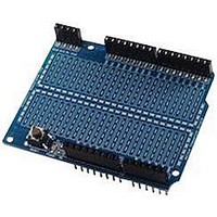
Amicus18 Companion Shield
Manufacturer
AMICUS
Datasheet
1.AMICUS18-COMPANION-SHIELD.pdf
(49 pages)
Specifications of AMICUS18-COMPANION-SHIELD
Silicon Manufacturer
Microchip
Core Architecture
PIC
Core Sub-architecture
PIC18
Features
USB Interface, In Circuit Serial Programming Interface
Kit Contents
Board
Silicon Family Name
PIC
Silicon Core Number
PIC18F25K20
Rohs Compliant
Yes
Lead Free Status / RoHS Status
Lead free / RoHS Compliant
For Use With
PIC18F25K20 Microcontroller


The circuit for the pulled-up switch input is shown below:
Open the Amicus IDE and type in the following program, or copy and paste from here:
' Demonstrate a switch input using a pull-up resistor
' Display state of the input pin RB4 when a push-button switch is operated
'
Click the toolbar icon
Amicus18’s microcontroller.
Open the Serial Terminal by clicking on the toolbar, and open a connection to the Amicus18. Use the
default baud of 9600. The serial terminal’s window should show the text “Button = 1”. This is dis-
playing the state of the pin where the button is attached. Press the button and the test will change to
“Button = 0”:
Crownhill AssociatesLimited 2009 - All Rights Reserved
Symbol Switch = RB4
Input Switch
While 1 = 1
Wend
HRSOut
DelayMS 500
"Button =
Compile and Program
Amicus18 Companion Shield
Version 1.0
", Bin1 Switch, 13
Button Released
Button Pressed
PortB
Power
GND
RB7
RB6
RB5
RB4
RB3
RB2
RB1
RB0
' Button is connected to RB4 (PortB.4)
' Make the button pin an input
' Create an infinite loop
' Delay for half a second
' Do it forever
or press F10 to build the code and place it into the
Button
22K
Push
LED
47
Ω
Ω
22
Resistor
Pull-Up
' Display the input state
Power
Vin
GND
GND
5V
3V3
Rst
06-10-2009
Related parts for AMICUS18-COMPANION-SHIELD
Image
Part Number
Description
Manufacturer
Datasheet
Request
R

Part Number:
Description:
Amicus18 Board
Manufacturer:
AMICUS
Datasheet:

Part Number:
Description:
AMIS30585AGAS-FSK PLC Modem
Manufacturer:
AMI Semiconductor
Datasheet:
Part Number:
Description:
Manufacturer:
AMI Semiconductor
Datasheet:
Part Number:
Description:
Programmable line lock clock generator IC
Manufacturer:
AMI Semiconductor
Datasheet:
Part Number:
Description:
PLL clock generator IC with VCXO
Manufacturer:
AMI Semiconductor
Datasheet:
Part Number:
Description:
Dual-PLL clock generator IC
Manufacturer:
AMI Semiconductor
Datasheet:
Part Number:
Description:
Two-way MP motherboard clock generator IC
Manufacturer:
AMI Semiconductor
Datasheet:
Part Number:
Description:
ADSL DMT Transceiver with ATM Framer and integrated controller
Manufacturer:
AMI Semiconductor
Part Number:
Description:
Integrated ADSL CMOS Analog Front-End Circuit
Manufacturer:
AMI Semiconductor
Datasheet: