E6486 QUANTUM ATMEL, E6486 Datasheet - Page 4
E6486
Manufacturer Part Number
E6486
Description
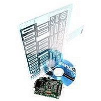
QT60486 And QT60326 Qtouch Evalution Kit
Manufacturer
QUANTUM ATMEL
Datasheet
1.E6486.pdf
(10 pages)
Specifications of E6486
Silicon Manufacturer
Atmel
Features
SPI High-speed Synchronous Communications, RS232 Primary Interface Interface
Kit Contents
Board And Literature
Silicon Family Name
Qmatrix
Silicon Core Number
QT60486, QT60326
Rohs Compliant
Yes
Lead Free Status / RoHS Status
Lead free / RoHS Compliant


BOARD DETAILS
Please refer to figure 2 on page 9
Power Terminal
This screw terminal strip is used to power the board. The voltage should be between +8 and +20VDC. Power
should be free from switching noise and short-term fluctuations for best performance. Be sure to check for low
voltage periodically if using a battery; low voltage will cause erratic performance.
RS232 (UART) Connector
This connector provides direct communications between the E6486 and the PC. It allows full control over the
device including calibration and setups. It also allows for real-time supervision of signal, reference and
calibration information. Use a straight-through type cable (supplied) — also known as an extender cable — to
a PC. The RS232 and SPI interfaces cannot operate at the same time.
Matrix Connector
The E6486 has two headers (J2 and J3). The pinout of both ports is described in table 1 (page 7). The header
provides the X-Y scanning of the matrix electrode. X lines drive charge into the matrix, and the Y lines conduct
the charge back out. The keyboard supplied with the kit can be connected directly to J3.
Communication Port Select
The UART port can either come from the RS232 connector or from J1. This
jumper allows the user to select the source of the UART signal.
SPI / UART Direct Port
J1 header gives access to all the signals useful for communicating with the QT60486 or QT60326. The pinout
of the connector is described below:
The QT60486/QT60326 can use either SPI or UART communications modes; it cannot use both at the same
time. The part defaults to SPI mode unless it receives a byte over the UART interface. If a UART byte is
received at any time, the UART interface is enabled and the SPI interface is totally disabled until after the next
device reset.
The QT60486 datasheet contains substantial additional information on communications.
Pin
1
2
3
4
5
6
7
8
9
10
11
12
13
14
J1
MISO
Vcc
SCK
MOSI
/RST
GND
n.c.
n.c.
/DRDY
/SS
Rx
Tx
WS
STATUS
Description
SPI - Data Input
Power; +5V
SPI - Clock Input
SPI - Data Output
Reset
Supply Ground
n.c.
n.c.
SPI - Data Ready
SPI - Slave Select
UART - Receive
UART - Transmit
Wake-up from sleep input / sync input
Status Output
J4
RS232
DIRECT
UART Source
RS232 Connector
J1
Related parts for E6486
Image
Part Number
Description
Manufacturer
Datasheet
Request
R

Part Number:
Description:
QT240 4 Key Qtouch Evaluation Kit
Manufacturer:
QUANTUM ATMEL
Datasheet:

Part Number:
Description:
EVALUATION KIT, MATRIX, 16/24 KEY
Manufacturer:
QUANTUM ATMEL
Datasheet:

Part Number:
Description:
IC SENSOR QTOUCH 4CHAN 20SSOP
Manufacturer:
Atmel
Datasheet:

Part Number:
Description:
QPROX SENSOR 24 KEYS, SMD, MLF-32
Manufacturer:
QUANTUM ATMEL
Datasheet:

Part Number:
Description:
KIT EVAL FOR AT42QT2160-MMU
Manufacturer:
Atmel
Datasheet:

Part Number:
Description:
KIT EVAL FOR AT42QT1060-MMU
Manufacturer:
Atmel
Datasheet:

Part Number:
Description:
KIT EVALUATION FOR AT42QT1040
Manufacturer:
Atmel
Datasheet:

Part Number:
Description:
KIT EVAL FOR QT100
Manufacturer:
Atmel
Datasheet:

Part Number:
Description:
EVAL BOARD FOR QT1103
Manufacturer:
Atmel
Datasheet:

Part Number:
Description:
BOARD EVALUATION FOR QT300
Manufacturer:
Atmel
Datasheet:
Part Number:
Description:
KIT EVAL/DEV USING QT102-ISG
Manufacturer:
Atmel
Datasheet:
Part Number:
Description:
KIT EVAL/DEV USING QT1081-ISG
Manufacturer:
Atmel
Datasheet:
Part Number:
Description:
QPROX SENSOR 24 KEYS, SMD, MLF-32
Manufacturer:
QUANTUM ATMEL
Datasheet:

Part Number:
Description:
IC, 16, 24 KEY QMATRIX SENSOR, TQFP-32
Manufacturer:
QUANTUM ATMEL
Datasheet:
Part Number:
Description:
QPROX SENSOR 16 KEYS, SMD, MLF-32
Manufacturer:
QUANTUM ATMEL
Datasheet: