E6486 QUANTUM ATMEL, E6486 Datasheet - Page 6
E6486
Manufacturer Part Number
E6486
Description
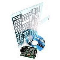
QT60486 And QT60326 Qtouch Evalution Kit
Manufacturer
QUANTUM ATMEL
Datasheet
1.E6486.pdf
(10 pages)
Specifications of E6486
Silicon Manufacturer
Atmel
Features
SPI High-speed Synchronous Communications, RS232 Primary Interface Interface
Kit Contents
Board And Literature
Silicon Family Name
Qmatrix
Silicon Core Number
QT60486, QT60326
Rohs Compliant
Yes
Lead Free Status / RoHS Status
Lead free / RoHS Compliant


Sync/Sleep
This input performs two functions: wake-up from sleep input, or noise synchronization input.
Wake from Sleep via UART: Link this input to the Rx line to enable wake from sleep via UART. In this mode,
the device will wake when a dummy transmission (a null byte) is received from the host over the UART RX
line. The logic level change of the UART RX line is used to create a wakeup logic input to the chip’s WS pin.
Wake from Sleep via SPI: Link this input to MOSI to enable wake from sleep via SPI. In this mode, the device
will wake when a dummy transmission (a null byte) is received from the host over the SPI lines. The logic level
change of the MOSI line is used to create a wakeup logic input to the chip’s WS pin.
External Wake from Sleep: Feed a minimum 5us sync pulse (normal logic high, pulse low) to pin 13 of J1 with
respect to GND to wake the part from a sleep state.
External Noise Sync: Feed a TTL or 5V CMOS synchronization pulse into pin 13 of J1 with respect to GND.
The QT60486 / QT60326 acquisition bursts can be synchronized to an external source of repetitive electrical
noise, such as 50Hz or 60Hz using the Noise Sync feature, which is enabled via Setups. External repetitive
signals are thereby heavily suppressed, since the system and the noise become synchronized and no longer
beat or alias with respect to each other. The sync input triggers the burst for key 0 (X0Y0); the device waits for
the sync signal for up to 100 ms after the end of a preceding full matrix scan (after key #47), then, when a sync
pulse is received, the matrix is scanned in its entirety one time. If no sync pulse is received in 100ms, the part
wakes on its own and re-scans the matrix one time then goes back to sleep. Sync pulses should be spaced no
more than 99ms apart to prevent this from happening.
Reset / Recal Button
This button causes a hard reset and a recalibration of all keys. The recalibrate button in QmBtn™ will also
accomplish a recalibration of all or some keys depending on current Scope. It is also possible to cause a hard
reset via QmBtn™.
Oscilloscope Sync
The ‘scope sync’ test point can be used to synchronize an oscilloscope. When enabled in QmBtn™, this signal
provides a pulse that brackets the chosen burst or bursts, making diagnostics much simpler. With the scope
sync enabled for one key, the X matrix drive signals can be clearly seen.
Status LED
The LED shows touch and error activity. If there is a calibration error or another type of fault, this LED will glow
solid. If the part is working normally, and no keys are detecting, the LED will be off. If one or more keys are
touched, the LED will flicker. The brightness of the flicker will be proportional to the number of keys detecting.
Cs Capacitors
The Cs capacitors, C12, C13, C14, C15, C17, C18 are the charge integrators that are used to detect changes
in key capacitance. Corresponding resistor network RN8 is used to convert the acquired charge to digital form.
These parts are optimal and should not be changed in value without a known reason.
Related parts for E6486
Image
Part Number
Description
Manufacturer
Datasheet
Request
R

Part Number:
Description:
QT240 4 Key Qtouch Evaluation Kit
Manufacturer:
QUANTUM ATMEL
Datasheet:

Part Number:
Description:
EVALUATION KIT, MATRIX, 16/24 KEY
Manufacturer:
QUANTUM ATMEL
Datasheet:

Part Number:
Description:
IC SENSOR QTOUCH 4CHAN 20SSOP
Manufacturer:
Atmel
Datasheet:

Part Number:
Description:
QPROX SENSOR 24 KEYS, SMD, MLF-32
Manufacturer:
QUANTUM ATMEL
Datasheet:

Part Number:
Description:
KIT EVAL FOR AT42QT2160-MMU
Manufacturer:
Atmel
Datasheet:

Part Number:
Description:
KIT EVAL FOR AT42QT1060-MMU
Manufacturer:
Atmel
Datasheet:

Part Number:
Description:
KIT EVALUATION FOR AT42QT1040
Manufacturer:
Atmel
Datasheet:

Part Number:
Description:
KIT EVAL FOR QT100
Manufacturer:
Atmel
Datasheet:

Part Number:
Description:
EVAL BOARD FOR QT1103
Manufacturer:
Atmel
Datasheet:

Part Number:
Description:
BOARD EVALUATION FOR QT300
Manufacturer:
Atmel
Datasheet:
Part Number:
Description:
KIT EVAL/DEV USING QT102-ISG
Manufacturer:
Atmel
Datasheet:
Part Number:
Description:
KIT EVAL/DEV USING QT1081-ISG
Manufacturer:
Atmel
Datasheet:
Part Number:
Description:
QPROX SENSOR 24 KEYS, SMD, MLF-32
Manufacturer:
QUANTUM ATMEL
Datasheet:

Part Number:
Description:
IC, 16, 24 KEY QMATRIX SENSOR, TQFP-32
Manufacturer:
QUANTUM ATMEL
Datasheet:
Part Number:
Description:
QPROX SENSOR 16 KEYS, SMD, MLF-32
Manufacturer:
QUANTUM ATMEL
Datasheet: