EM-LPC1300 EMBEST, EM-LPC1300 Datasheet - Page 15
EM-LPC1300
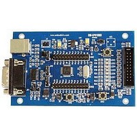
Manufacturer Part Number
EM-LPC1300
Description
NXP LPC1300 ARM Cortex-M3 Evaluation Board
Manufacturer
EMBEST
Datasheet
1.EM-LPC1300.pdf
(26 pages)
Specifications of EM-LPC1300
Silicon Manufacturer
NXP
Core Architecture
ARM
Core Sub-architecture
Cortex-M3
Features
RS232, USB, JTAG Interface, 12MHz XTAL Frequency
Silicon Core Number
LPC13xx
Silicon Family Name
LPC13xx


4.7 UART test
4.8 USB CDC test
4.9 USB HID test
LED1 on the board start to blinky immediately after reset.
Reference manual: EM-LPC13xx Reference Manual.pdf
Source code location: 03-software\Examples\07-UART
Test description: This example describes how to use UART to send and receive data through
HyperTerminal.
Test phenomenon: Build the program and download it inside the evaluation board. Open PC
HyperTerminal and push RESET button, you will see the phenomenon below.
Input any key using PC keyboard, the corresponding letter will display in the HyperTerminal.
Reference manual: EM-LPC13xx Reference Manual.pdf, MAX3232CSE.pdf
Source code location: 03-software\Examples\08-USB_CDC
Test description: The Virtual COM port project is a demo program for using the EM-LPC1300 board. It
demonstrates an USB Virtual COM port based on a Windows USB host driver (usbser.sys).
Test phenomenon: Connnect board with PC COM using USB cable. Build the program and download
it inside the evaluation board. Push RESET button.The PC will install a virtual COM port on the PC
(see Driver Installation).You can find drive file in directory drive/lpc134x-vcom.inf. After installation
an additional port "LPC13xx USB VCom Port(COMx)" can be found under System/Hardware/Device
Manager/Ports(COM&LPT). Number "x" is not fixed as different PC configuration may have different
"x" displayed on the device manager. The USB host driver assigns "x" dynamically based on the
existing COM port configuration of the system. Open two Hyperterminal windows.One with
"LPC13xx USB VCom Port(COMx)" .One with "Communications Port (COM1)".Connect PC port
COM1 to the comport on the board and open "COM1" and "COMx". Data from COM1 will be echoed
on "COMx" and visa versa. So, this is bi-directional communication between the physical COM port 1
on the board and the virtual COM port COMx on host PC.
Reference manual: EM-LPC13xx Reference Manual.pdf
Source code location: 03-software\Examples\09-USB_HID
Test description: The HID(Human Interface Device) project is a demo program using the
EM-LPC1300 board.
Test phenomenon: Connnect board with PC COM using USB cable. Build the program and download
it inside the evaluation board. Push RESET button. The USB HID is recognized by the host PC running
Windows which will load a generic HID driver. The board LEDs can then be accessed from the PC
through a custom HID Client Program(hidTest.exe). You can check the Vendor ID, Product ID,Version
-- EM-LPC1300 --
-- LED1 blinky delay controled by timer32 test --
-- Basic UART Project V1.0 --
-- EM-LPC1300 --
-- Please input any key on the keyboard --
www.embedinfo.com/en
15/26
Related parts for EM-LPC1300
Image
Part Number
Description
Manufacturer
Datasheet
Request
R

Part Number:
Description:
MIC OMNI .9-10VDC -36DB SENS
Manufacturer:
Knowles Acoustics
Datasheet:
Part Number:
Description:
MIC OMNI .9-10VDC -38.5DB SENS
Manufacturer:
Knowles Acoustics
Datasheet:

Part Number:
Description:
MIC ELECTRET OMNI HIGH SENSITVTY
Manufacturer:
Knowles Acoustics
Datasheet:

Part Number:
Description:
MIC ELECTRET OMNI HISENS W/LEADS
Manufacturer:
Knowles Acoustics
Datasheet:
Part Number:
Description:
Microphone
Manufacturer:
Knowles Acoustics
Datasheet:
Part Number:
Description:
Microphones 3.61 X 3.61 X 2.21MM -68.5 SENS, 12B PORT
Manufacturer:
Knowles Acoustics
Datasheet:
Part Number:
Description:
Microphones 3.61 X 3.61 X 2.21MM -56 SENS, 12B PORT
Manufacturer:
Knowles Acoustics
Datasheet:
Part Number:
Description:
Microphones 3.61 X 3.61 X 2.21MM -56 SENS, 12SL PORT
Manufacturer:
Knowles Acoustics
Datasheet:
Part Number:
Description:
Microphones 3.61 X 3.61 X 2.21MM -58 SENS, 12SL PORT
Manufacturer:
Knowles Acoustics
Datasheet:
Part Number:
Description:
Microphones 3.61 X 3.61 X 2.21MM -52 SENS 12KP PORT
Manufacturer:
Knowles Acoustics
Datasheet:
