EM-LPC1300 EMBEST, EM-LPC1300 Datasheet - Page 17
EM-LPC1300
Manufacturer Part Number
EM-LPC1300
Description
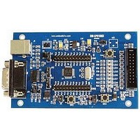
NXP LPC1300 ARM Cortex-M3 Evaluation Board
Manufacturer
EMBEST
Datasheet
1.EM-LPC1300.pdf
(26 pages)
Specifications of EM-LPC1300
Silicon Manufacturer
NXP
Core Architecture
ARM
Core Sub-architecture
Cortex-M3
Features
RS232, USB, JTAG Interface, 12MHz XTAL Frequency
Silicon Core Number
LPC13xx
Silicon Family Name
LPC13xx


4.12 USB Memory Storage Rom test
4.13 WDT test
Test phenomenon: Connnect board with PC COM using USB cable. Build the program and download
it inside the evaluation board. Push RESET button. The USB Memory is automatically recognized by
the host PC running Windows which will load a generic Mass Storage driver. Then you can find this
device in PC hardware list. Open “my computer” icon on your desktop. You can find a new removable
storage devices with name “LPC134x USB”. You can also open a readme.txt file from this device. The
content of this file is the brief information about this demo.
Reference manual: EM-LPC13xx Reference Manual.pdf
Source code location: 03-software\Examples\12-USB_Mem_rom
Test description: The Memory project is a demo program for the Embest EM-LPC1300 Board using
the NXP LPC1343 Microcontroller. It demonstrates an USB Memory based on USB Mass Storage
Class. The only difference is that pll and pin init function program used are all placed in the BOOT
ROM. They are download by ULINK2 or other debugging tools previously and their memory address
are determined at the compile time.
Test phenomenon: Connnect board with PC COM using USB cable. Build the program and download
it inside the evaluation board. Push RESET button. The USB Memory is automatically recognized by
the host PC running Windows which will load a generic Mass Storage driver. Then you can find this
device in PC hardware list. Open “my computer” icon on your desktop. You can find a new removable
storage devices with name “LPC134x USB”. You can also open a readme.txt file from this device. The
content of this file is the brief information about this demo. The detail phenomenon are same to 4.11.
Reference manual: EM-LPC13xx Reference Manual.pdf
Source code location: 03-Software\Examples\13-WDT
Test description: This example describes how to configure and use WDT. The Watchdog will generate
a system reset if the user program fails to "feed" (or reload) the Watchdog within a predetermined
amount of time. Writing 0xAA followed by 0x55 to WDFEED(Watchdog feed sequence register)
reloads the Watchdog timer with the value contained in WDTC(Watchdog timer constant register).
Test phenomenon: Build the program and download it inside the evaluation board. Open PC
HyperTerminal and push RESET button, you will see the phenomenon below.
LED1 starts blinky after reset. Press BOOT button, WatchDog can’t be feeded, so it resets system.
After system reset, LED1…8 are all turned on and LED1 resume blinky. Description Information is
displayed in the terminal.
-- Basic WDT Project V1.0 --
-- EM-LPC1300 --
-- Feed watchdog timer to prevent it from timeout test --
PIOINT0_IRQHandler!
-- Basic WDT Project V1.0 --
-- EM-LPC1300 --
-- Feed watchdog timer to prevent it from timeout test --
www.embedinfo.com/en
17/26
Related parts for EM-LPC1300
Image
Part Number
Description
Manufacturer
Datasheet
Request
R

Part Number:
Description:
MIC OMNI .9-10VDC -36DB SENS
Manufacturer:
Knowles Acoustics
Datasheet:
Part Number:
Description:
MIC OMNI .9-10VDC -38.5DB SENS
Manufacturer:
Knowles Acoustics
Datasheet:

Part Number:
Description:
MIC ELECTRET OMNI HIGH SENSITVTY
Manufacturer:
Knowles Acoustics
Datasheet:

Part Number:
Description:
MIC ELECTRET OMNI HISENS W/LEADS
Manufacturer:
Knowles Acoustics
Datasheet:
Part Number:
Description:
Microphone
Manufacturer:
Knowles Acoustics
Datasheet:
Part Number:
Description:
Microphones 3.61 X 3.61 X 2.21MM -68.5 SENS, 12B PORT
Manufacturer:
Knowles Acoustics
Datasheet:
Part Number:
Description:
Microphones 3.61 X 3.61 X 2.21MM -56 SENS, 12B PORT
Manufacturer:
Knowles Acoustics
Datasheet:
Part Number:
Description:
Microphones 3.61 X 3.61 X 2.21MM -56 SENS, 12SL PORT
Manufacturer:
Knowles Acoustics
Datasheet:
Part Number:
Description:
Microphones 3.61 X 3.61 X 2.21MM -58 SENS, 12SL PORT
Manufacturer:
Knowles Acoustics
Datasheet:
Part Number:
Description:
Microphones 3.61 X 3.61 X 2.21MM -52 SENS 12KP PORT
Manufacturer:
Knowles Acoustics
Datasheet:
