AC164139 Microchip Technology, AC164139 Datasheet - Page 354
AC164139
Manufacturer Part Number
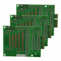
AC164139
Description
Graphics Display Prototype Board Graphics
Manufacturer
Microchip Technology
Specifications of AC164139
Main Purpose
LCD Development
Embedded
No
Utilized Ic / Part
PICtail™ Plus Board
Lead Free Status / RoHS Status
Lead free / RoHS Compliant
Secondary Attributes
-
Primary Attributes
-
Lead Free Status / RoHS Status
Lead free / RoHS Compliant
Available stocks
Company
Part Number
Manufacturer
Quantity
Price
Company:

Part Number:
AC164139
Manufacturer:
Microchip Technology
Quantity:
135


PIC24FJ256DA210 FAMILY
REGISTER 27-6:
27.2
All PIC24FJ256DA210 family devices power their core
digital logic at a nominal 1.8V. This may create an issue
for designs that are required to operate at a higher
typical voltage, such as 3.3V. To simplify system
design, all devices in the PIC24FJ256DA210 family
incorporate an on-chip regulator that allows the device
to run its core logic from V
The regulator is controlled by the ENVREG pin. Tying V
to the pin enables the regulator, which in turn, provides
power to the core from the other V
ulator is enabled, a low-ESR capacitor (such as ceramic)
must be connected to the V
helps to maintain the stability of the regulator. The recom-
mended value for the filter capacitor (C
Section 30.1 “DC Characteristics”.
27.2.1
When the on-chip regulator is enabled, it provides a
constant voltage of 1.8V nominal to the digital core
logic.
The regulator can provide this level from a V
2.1V, all the way up to the device’s V
have the capability to boost V
vent “brown-out” conditions when the voltage drops too
low for the regulator, the Brown-out Reset occurs. Then
the regulator output follows V
drop of 300 mV.
To provide information about when the regulator
voltage starts reducing, the on-chip regulator includes
a simple Low-Voltage Detect circuit, which sets the
DS39969B-page 354
bit 23
bit 15
bit 7
Legend: R = Readable bit
bit 23-4
bit 3-0
U-0
U-0
U-0
—
—
—
On-Chip Voltage Regulator
VOLTAGE REGULATOR
LOW-VOLTAGE DETECTION
Unimplemented: Read as ‘0’
REV<3:0>: Device revision identifier bits
U-0
U-0
U-0
—
—
—
DEVREV: DEVICE REVISION REGISTER
DD
CAP
.
DD
DD
DD
pin (Figure 27-1). This
levels. In order to pre-
with a typical voltage
pins. When the reg-
U-0
U-0
U-0
DDMAX
—
—
—
EFC
) is provided in
. It does not
DD
of about
U-0
U-0
U-0
—
—
—
DD
U = Unimplemented bit
REV3
Low-Voltage Detect Interrupt Flag, LVDIF (IFS4<8>).
This can be used to generate an interrupt to trigger an
orderly shutdown.
FIGURE 27-1:
27.2.2
When the voltage regulator is enabled, it takes approx-
imately 10 s for it to generate output. During this time,
designated as T
T
operation after any power-down, including Sleep mode.
T
(RCON<8>) and the WUTSEL Configuration bits
(CW3<11:10>). Refer to Section 30.0 “Electrical
Characteristics” for more information on T
U-0
U-0
—
—
VREG
VREG
R
Note 1:
Regulator Enabled (ENVREG tied to V
(10 F typ)
is determined by the status of the VREGS bit
is applied every time the device resumes
C
EFC
ON-CHIP REGULATOR AND POR
This is a typical operating voltage. Refer to
Section 30.1 “DC Characteristics” for
the full operating ranges of V
REV2
U-0
U-0
3.3V
—
—
R
VREG
(1)
CONNECTIONS FOR THE
ON-CHIP REGULATOR
, code execution is disabled.
2010 Microchip Technology Inc.
V
ENVREG
V
V
DD
CAP
SS
PIC24FJXXXDA1/DA2
REV1
U-0
U-0
—
—
R
DD
.
DD
VREG
REV0
):
U-0
U-0
—
—
R
bit 16
.
bit 8
bit 0
Related parts for AC164139
Image
Part Number
Description
Manufacturer
Datasheet
Request
R

Part Number:
Description:
Manufacturer:
Microchip Technology Inc.
Datasheet:
Part Number:
Description:
Manufacturer:
Microchip Technology Inc.
Datasheet:
Part Number:
Description:
Manufacturer:
Microchip Technology Inc.
Datasheet:
Part Number:
Description:
Manufacturer:
Microchip Technology Inc.
Datasheet:
Part Number:
Description:
Manufacturer:
Microchip Technology Inc.
Datasheet:
Part Number:
Description:
Manufacturer:
Microchip Technology Inc.
Datasheet:
Part Number:
Description:
Manufacturer:
Microchip Technology Inc.
Datasheet:
Part Number:
Description:
Manufacturer:
Microchip Technology Inc.
Datasheet: