10-142 Cinch Connectors, 10-142 Datasheet
10-142
Specifications of 10-142
10142
CBB310


Related parts for 10-142


10-142 Summary of contents
Page 1
Catalog No. C-865 ...
Page 2
CIN::APSE High Speed Interconnect Technology ® ...
Page 3
... Packaging Tray Material: Anti-static ABS Button-Only Configuration with 0.020" (0.5 mm) Diameter Temperature Life Testing: 1000 Hours @ 200°C Thermal Shock: 2,000 Cycles @ 20°C to 110°C Humidity: 5,000 Hours @ 30°C to 80°C, 80% RH Salt Spray: 96 Hours Low Temperature: Operates in liquid nitrogen (77°K) Bellcore TR-NWT-001217: Passed with plungers Button-Only Configuration with 0.020" ...
Page 4
CIN::APSE ® High-Speed Interconnect Technology THE BUTTON CONTACT The unique construction of the CIN::APSE contact provides superior mechanical and electrical performance constructed of randomly wound molybdenum wire that is formed into a cyclindrical shape. Standard CIN::APSE contact diameters ...
Page 5
CIN::APSE ® High-Speed Interconnect Technology 1 TYPICAL CONFIGURATION 1. Button-Only This is the basic CIN::APSE contact configuration ideally suited for z-axis applications requiring minimum height, high density, and signal integrity. This configuration is used in LGA and IC ...
Page 6
CIN::APSE ® High-Speed Interconnect Technology VARIOUS CIN::APSE APPLICATIONS IC Component to Board Socket (LGA) Hybrid Circuit to Flex to PCB Cable to PCB/Flex PCB to PCB LCD to Flex to PCB Flex Circuit to PCB Call Toll Free: 1 (800) ...
Page 7
COMMERCIAL Barrier Blocks Circular Mini DIN BNC Jones Plugs Edge Connectors ...
Page 8
... Cinch Edge Card Connectors are available in a variety of styles on both .100 or .156 center spacing. The newest addition to the commercial family, the 75Ω Press-Fit BNC Receptacle is designed around a unique patented press-fit design that allows for multiple insertion into a backplane without loss of mechanical retention or electrical performance ...
Page 9
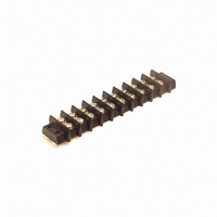
Barrier Blocks Interposing barriers between terminals yield higher electrical ratings and provide additional protection against frayed wire shorting. A wide variety of barrier blocks makes it possible to select the combination of mechanical and electrical characteristics that best meet the ...
Page 10
... Volts 15 Amps #16 3750 Call Toll Free: 1 (800) 323-9612 2-3 Voltage Voltage Marker Rating Rating Strip w/Marker w/o Marker Mounting 2000 1100 Bottom 2400 1100 Bottom 2600 1600 Bottom 2400 1500 Bottom 3400 1800 Bottom 3800 2100 Bottom 2000 1100 Bottom 2300 ...
Page 11
... Dim. 1.032 1.407 1.782 2.157 2.532 2.907 3.282 3.657 4.032 4.407 4.782 5.157 5.532 5.907 6.282 6.657 7.032 7.407 7.782 8.157 8.532 8.907 9.282 9.657 10.032 Marketed exclusively through distribution. ...
Page 12
... Catalog No. Y-140 3/4W-140 W-140 2-5 “W” Terminals Catalog No. 1-140-W 2-140-W 3-140-W 4-140-W 5-140-W 6-140-W 7-140-W 8-140-W 9-140-W 10-140-W 11-140-W 12-140-W 13-140-W 14-140-W 15-140-W 16-140-W 17-140-W 18-140-W 19-140-W 20-140-W 21-140-W 22-140-W 23-140-W 24-140-W 25-140-W Marketed exclusively through distribution. Call Toll Free: 1 (800) 323-9612 ...
Page 13
... Catalog No. MS-1-140 MS-1-140-Y MS-2-140 MS-2-140-Y MS-3-140 MS-3-140-Y MS-4-140 MS-4-140-Y MS-5-140 MS-5-140-Y MS-6-140 MS-6-140-Y MS-7-140 MS-7-140-Y MS-8-140 MS-8-140-Y MS-9-140 MS-9-140-Y MS-10-140 MS-10-140-Y MS-11-140 MS-11-140-Y MS-12-140 MS-12-140-Y MS-13-140 MS-13-140-Y MS-14-140 MS-14-140-Y MS-15-140 MS-15-140-Y MS-16-140 MS-16-140-Y MS-17-140 MS-17-140-Y MS-18-140 MS-18-140-Y MS-19-140 MS-19-140-Y MS-20-140 MS-20-140-Y ...
Page 14
... Catalog No. Dim. 1-141 .875 2-141 1.312 3-141 1.750 4-141 2.187 5-141 2.625 6-141 3.062 7-141 3.500 8-141 3.938 9-141 4.375 10-141 4.813 11-141 5.250 12-141 5.687 13-141 6.125 14-141 6.562 15-141 7.000 16-141 7.437 17-141 7.875 18-141 8.312 19-141 8.750 20-141 9 ...
Page 15
... Catalog No. 1-141-3/4W 1-141-W 2-141-3/4W 2-141-W 3-141-3/4W 3-141-W 4-141-3/4W 4-141-W 5-141-3/4W 5-141-W 6-141-3/4W 6-141-W 7-141-3/4W 7-141-W 8-141-3/4W 8-141-W 9-141-3/4W 9-141-W 10-141-3/4W 10-141-W 11-141-3/4W 11-141-W 12-141-3/4W 12-141-W 13-141-3/4W 13-141-W 14-141-3/4W 14-141-W 15-141-3/4W 15-141-W 16-141-3/4W 16-141-W 17-141-3/4W 17-141-W 18-141-3/4W 18-141-W 19-141-3/4W 19-141-W 20-141-3/4W 20-141-W Catalog No ...
Page 16
... MS-3-141 MS-3-141-Y MS-4-141 MS-4-141-Y MS-5-141 MS-5-141-Y MS-6-141 MS-6-141-Y MS-7-141 MS-7-141-Y MS-8-141 MS-8-141-Y MS-9-141 MS-9-141-Y MS-10-141 MS-10-141-Y MS-11-141 MS-11-141-Y MS-12-141 MS-12-141-Y MS-13-141 MS-13-141-Y MS-14-141 MS-14-141-Y MS-15-141 MS-15-141-Y MS-16-141 MS-16-141-Y MS-17-141 MS-17-141-Y MS-18-141 MS-18-141-Y MS-19-141 MS-19-141-Y MS-20-141 MS-20-141-Y 2-10 Marketed exclusively through distribution. ...
Page 17
... Catalog No. Dim. 1-142 1.125 2-142 1.687 3-142 2.250 4-142 2.812 5-142 3.375 6-142 3.937 7-142 4.500 8-142 5.062 9-142 5.625 10-142 6.187 11-142 6.750 12-142 7.312 13-142 7.875 14-142 8.437 15-142 9.000 16-142 9.562 17-142 10.125 2-12 “L” Dim. 1.531 2 ...
Page 18
... Catalog No. Y-142 3/4W-142 W-142 2-13 “W” Terminals Catalog No. 1-142-W 2-142-W 3-142-W 4-142-W 5-142-W 6-142-W 7-142-W 8-142-W 9-142-W 10-142-W 11-142-W 12-142-W 13-142-W 14-142-W 15-142-W 16-142-W 17-142-W Marketed exclusively through distribution. Call Toll Free: 1 (800) 323-9612 ...
Page 19
... MS-1-142-Y MS-2-142 MS-2-142-Y MS-3-142 MS-3-142-Y MS-4-142 MS-4-142-Y MS-5-142 MS-5-142-Y MS-6-142 MS-6-142-Y MS-7-142 MS-7-142-Y MS-8-142 MS-8-142-Y MS-9-142 MS-9-142-Y MS-10-142 MS-10-142-Y MS-11-142 MS-11-142-Y MS-12-142 MS-12-142-Y MS-13-142 MS-13-142-Y MS-14-142 MS-14-142-Y MS-15-142 MS-15-142-Y MS-16-142 MS-16-142-Y MS-17-142 MS-17-142-Y 2-14 “Y” Terminal Marketed exclusively through distribution. ...
Page 20
... Density, 10-32 x 5/16" Barrier Blocks BH Screw, Open Bottom, Series 150 Double Row Electrical Characteristics Voltage Rating: 250 VAC RMS maximum Current Rating: 40 Amps maximum Maximum Watts Per Terminal: 10,000 Mechanical Characteristics Maximum Wire Size: #10 AWG Recommended Tightening Torque: 20 lb.-in. ...
Page 21
... Dimensions Standard .688 TYP (17.46) Ordering Information No. of Terminals Accessories None Available for 150 Series. .688 Density, 10-32 x 5/16" BH Screw, Open Bottom, Double Row Catalog No. Catalog No. MS-1-150 MS-1-150-Y MS-2-150 MS-2-150-Y MS-3-150 MS-3-150-Y MS-4-150 MS-4-150-Y MS-5-150 MS-5-150-Y MS-6-150 MS-6-150-Y MS-7-150 MS-7-150-Y MS-8-150 ...
Page 22
Barrier Blocks Series 151 Electrical Characteristics Voltage Rating: 250 Volts maximum Current Rating: 50 Amps maximum Maximum Watts Per Terminal: 12,500 Mechanical Characteristics Maximum Wire Size: #8 Recommended Tightening Torque: 40 lb.-in. Dimensions Ordering Information No. of Terminals Catalog No. ...
Page 23
Barrier Blocks Series 152 Electrical Characteristics Voltage Rating: 250 Volts maximum Current Rating: 70 Amps maximum Maximum Watts Per Terminal: 54,000 Mechanical Characteristics Maximum Wire Size: #6 Recommended Tightening Torque: 75 lb.-in. Dimensions Ordering Information No. of Terminals Catalog No. ...
Page 24
... Catalog No. Dim. (in) 1-164 0.750 2-164 1.125 3-164 1.500 4-164 1.875 5-164 2.250 6-164 2.625 7-164 3.000 8-164 3.375 9-164 3.750 10-164 4.125 11-164 4.500 12-164 4.875 13-164 5.250 14-164 5.625 15-164 6.000 16-164 6.375 17-164 6.750 18-164 7.125 19-164 7.500 20-164 7 ...
Page 25
... Terminals Catalog No. 1-164-W 2-164-W 3-164-W 4-164-W 5-164-W 6-164-W 7-164-W 8-164-W 9-164-W 10-164-W 11-164-W 12-164-W 13-164-W 14-164-W 15-164-W 16-164-W 17-164-W 18-164-W 19-164-W 20-164-W 21-164-W Marketed exclusively through distribution. Call Toll Free: 1 (800) 323-9612 ...
Page 26
... Catalog No. N/A N/A MS-2-140 MS-2-140-Y MS-3-140 MS-3-140-Y MS-4-140 MS-4-140-Y MS-5-140 MS-5-140-Y MS-6-140 MS-6-140-Y MS-7-140 MS-7-140-Y MS-8-140 MS-8-140-Y MS-9-140 MS-9-140-Y MS-10-140 MS-10-140-Y MS-11-140 MS-11-140-Y MS-12-140 MS-12-140-Y MS-13-140 MS-13-140-Y MS-14-140 MS-14-140-Y MS-15-140 MS-15-140-Y MS-16-140 MS-16-140-Y MS-17-140 MS-17-140-Y MS-18-140 MS-18-140-Y MS-19-140 MS-19-140-Y MS-20-140 MS-20-140-Y ...
Page 27
... MSX-13-540 5.907 MSX-14-540 6.282 MSX-15-540 6.657 MSX-16-540 7.032 MSX-17-540 7.407 MSX-18-540 7.782 MSX-19-540 8.157 MSX-20-540 8.532 MSX-21-540 8.907 MSX-22-540 9.282 MSX-23-540 9.657 MSX-24-540 10.032 MSX-25-540 10.407 MSX-26-540 10.782 MSX-27-540 11.157 MSX-28-540 11.532 MSX-29-540 11.907 MSX-30-540 12.282 MSX-31-540 Marketed exclusively through distribution. ...
Page 28
... Marker Strip Catalog No. MSX-2-541 MSX-3-541 ...
Page 29
... Barrier Blocks Series 542 Electrical Characteristics Voltage Rating: 600 Volts maximum Current Rating: 30 Amps Maximum Watts Per Terminal: 7500 Mechanical Characteristics Maximum Wire Size: #10 Recommended Tightening Torque: 16 lb.-in. Dimensions Ordering Information No. of Terminals Catalog No 10-542 11 11-542 12 12-542 13 13-542 14 14-542 15 15-542 16 16-542 ...
Page 30
... Tail Lgth Dimension 2-176-3 1.125 3-176-3 1.500 4-176-3 1.875 5-176-3 2.250 6-176-3 2.625 7-176-3 3.000 8-176-3 3.375 9-176-3 3.375 10-176-3 4.125 Catalog No. .184 Tail Lgth Dimension 2-176-3A 3-176-3A 1.094 4-176-3A 1.469 5-176-3A 1.844 6-176-3A 2.219 7-176-3A 2.594 8-176-3A 2.969 9-176-3A 3 ...
Page 31
... .593 15.06 .093 2.36 .091 .781 19.83 .125 3.18 .103 .906 23.01 .125 3.18 .126 .063 1.60 .146 3.71 .094 .078 1.98 .152 3.86 .125 .094 2.39 .177 4.50 ...
Page 32
... E 142J-2 540 C 540J 541 C 541J 542 C 542J * Connects two alternate terminals Screw Wire Gauge Size Range AWG 12 thru 22 10 thru 16 Type A Type D 2-29 QC-1 Shown Type B Type C Type F Type E Marketed exclusively through distribution. Call Toll Free: 1 (800) 323-9612 2 ...
Page 33
Barrier Block Accessories Minimize wiring errors. Available in straight and right-angle styles. Available with cable clamp hole on right or left side, designated by “L” or “R” at end of catalog number. Cable clamp hole for securing cable/wires with lacing ...
Page 34
... Marketed exclusively through distribution. 2-31 Catalog No. 2-160B-L 3-160B-L 4-160B-L 5-160B-L 6-160B-L 7-160B-L 8-160B-L 9-160B-L 10-160B-L 11-160B-L 12-160B-L 13-160B-L 14-160B-L 15-160B-L 16-160B-L 17-160B-L 18-160B-L 19-160B-L 20-160B-L 21-160B-L Call Toll Free: 1 (800) 323-9612 ...
Page 35
... Catalog No. 2-160A-L 3-160A-L 4-160A-L 5-160A-L 6-160A-L 7-160A-L 8-160A-L 9-160A-L 10-160A-L 11-160A-L 12-160A-L 13-160A-L 14-160A-L 15-160A-L 16-160A-L 17-160A-L 18-160A-L 19-160A-L 20-160A-L 21-160A-L Marketed exclusively through distribution. ...
Page 36
... No. of Terminals Catalog No. Catalog No. 2 2-161A-R 2-161A-L 3 3-161A-R 3-161A-L 4 4-161A-R 4-161A-L 5 5-161A-R 5-161A-L 6 6-161A-R 6-161A-L 7 7-161A-R 7-161A-L 8 8-161A-R 8-161A-L 9 9-161A-R 9-161A-L 10 10-161A-R 10-161A-L 11 11-161A-R 11-161A-L 12 12-161A-R 12-161A-L 13 13-161A-R 13-161A-L 14 14-161A-R 14-161A-L 15 15-161A-R 15-161A-L 16 16-161A-R 16-161A-L 17 17-161A-R 17-161A-L 18 18-161A-R 18-161A-L 19 19-161A-R 19-161A-L ...
Page 37
... Call Toll Free: 1 (800) 323-9612 Fanning Strips Catalog No. 2-162-L 3-162-L 4-162-L 5-162-L 6-162-L 7-162-L 8-162-L 9-162-L 10-162-L 11-162-L 12-162-L 13-162-L 14-162-L 15-162-L 16-162-L 17-162-L Catalog No. 2-162A-L 3-162A-L 4-162A-L 5-162A-L 6-162A-L 7-162A-L 8-162A-L 9-162A-L 10-162A-L 11-162A-L 12-162A-L ...
Page 38
... Dimensions Lug-Type Terminal Strips ...
Page 39
... See Panel Cutout dimension on page (2-38). Insulation Material: Molded monoblock, general purpose phenolic, black UL94V-1 Contact Material: Plug: Brass Socket: Phosphor bronze Contact Plating: Cadmium Operating Temperature +105°C Hood Material: UL 94V-0 rated thermoplastic Operating Voltage: Current Rating: Contact Resistance: Call Toll Free: 1 (800) 323-9612 ...
Page 40
Jones Plugs/Sockets Series 300 Polarizing Patterns - 300 Series Multiple Density Solder Eyelet Marketed exclusively through distribution. Call Toll Free: 1 (800) 323-9612 2-37 ...
Page 41
... Plugs/Sockets Series 300 All-Plastic Mounting Dimensions A Reference in mm 303 .453 11.51 304 .719 18.26 306 .719 18.26 2 308 .719 18.26 310 .719 18.26 312 .953 24.21 315-12 .953 24.21 315 1.016 25.81 318 1.016 25.81 321 1.016 25.81 324 1.016 25.81 327 1 ...
Page 42
... NOTE: 15-position plug and socket require only two mounting brackets, mounted on center of connector. [.050” (1.27mm) Density Multiple Density Solder Cup/Wire Solder Eyelet With Angle D-Microminiature] Bracket/Less Angle Bracket No. of Catalog No. Contacts 2 P-302-LAB 3 P-303-LAB 4 P-304-LAB 6 P-306-LAB 8 10 P-310-LAB 12 P-312-LAB 15 15 P-315-LAB 18 P-318-LAB 21 P-321-LAB 24 P-324-LAB 27 P-327-LAB 30 P-330-LAB 33 P-333-LAB X = length of plug contacts ...
Page 43
... Panel Cutout Dimensions Reference 303-FP 304-FP 306-FP 308-FP 310-FP 312-FP Call Toll Free: 1 (800) 323-9612 [.050” (1.27mm) Density Multiple Density Solder Cup/Wire Solder Eyelet D-Microminiature] Flush Plate Catalog No. Socket S-302-FP S-303-FP S-304-FP S-306-FP N/A N/A N length of plug contacts ...
Page 44
... P Polarizing Pin 41.28 NO 49.23 NO 57.15 NO 65.10 14 73.03 14 80.98 14 88. 2.000 50.80 2.313 58.75 2.625 66.68 2.938 74.63 3.250 82.55 3.563 90.50 3.875 98.43 Marketed exclusively through distribution. ...
Page 45
... Call Toll Free: 1 (800) 323-9612 Multiple Density Solder Eyelet Recessed Plate Catalog No. Socket S-302-RP S-303-RP S-304-RP S-306-RP N/A N/A N 1.500 38.10 1.750 1.500 38.10 1.750 1.500 38.10 1.750 1.500 38.10 1.750 -- -- -- 2.000 50.80 2.250 2.000 50.80 2.250 2- Max 44.45 1 ...
Page 46
... Polarizing in mm Pin 2.547 64.69 NO 2.859 72.62 NO 3.172 80.57 NO 3.484 88.49 14 3.797 96.44 14 4.109 104.38 14 4.422 112. 2.125 53.98 2.438 61.93 2.750 69.85 3.062 77.77 3.376 85.75 3.688 93.68 4.000 101.60 Marketed exclusively through distribution. Call Toll Free: 1 (800) 323-9612 2 ...
Page 47
... Y = length of plug or socket tails. Polarizing mm Pin 60.33 NO 68.28 NO 76.20 NO 84.15 14 92. 1.750 38.10 2.376 60.35 2.688 68.28 3.000 76.20 3.312 84.12 3.626 92.10 3.938 100.03 4.250 107.95 Marketed exclusively through distribution. ...
Page 48
... 63.85 1.795 45.59 71.78 2.107 53.52 79.73 2.420 61.47 87.66 2.732 69.39 95.61 3.045 77.34 103.53 3.357 85.27 111.48 3.670 93.22 2-45 G Cable "D" Opening .313 7.95 .313 .344 8.74 .250 .453 11.51 .375 .469 11.91 .438 ...
Page 49
... L Cable Opening 1.795 45.59 .563 14.30 2.107 53.52 .563 14.30 2.420 61.47 .625 15.88 2.732 69.39 .625 15.88 3.045 77.34 .625 15.88 3.357 85.27 .750 19.05 3.670 93.22 .750 19.05 2-46 E ± ...
Page 50
... Multiple Density Solder Eyelet 180° Clamp w/Locks N/A N/A N/A Plug B ± .016 C ± .031 ( ...
Page 51
... Call Toll Free: 1 (800) 323-9612 [.050” (1.27mm) Density Multiple Density Solder Cup/Wire Solder Eyelet D-Microminiature] PLUGS ...
Page 52
... Panel cutout dimensions (See page 2-57). Insulation Material: Molded monoblock, general purpose phenolic, black Contact Material: Plug: Brass Socket: Phosphor bronze Contact Plating: Cadmium Operating Temperature +105°C Hood Material: Formed metal with dielectric liner in hood to prevent shorting Operating Voltage: Current Rating: Current Resistance: ...
Page 53
... S-2404-LAB 6 P-2406-LAB S-2406-LAB 8 P-2408-LAB S-2408-LAB 10 P-2410-LAB S-2410-LAB 12 P-2412-LAB S-2412-LAB Plug Dimensions - Plug or Socket No. of Contacts 2 .563 4 1.000 6 1.438 8 1.875 10 2.313 12 2.750 Multiple Density Solder Eyelet Less Angle Bracket Socket Socket 14.29 .656 16.67 25.40 1.094 27.78 36.51 1.531 38.89 47.63 1.969 50 ...
Page 54
... Panel Cutout dimensions are on page 2-61. Call Toll Free: 1 (800) 323-9612 [.050” (1.27mm) Density Multiple Density Solder Cup/Wire Solder Eyelet D-Microminiature] With Angle Bracket Catalog No. Socket S-2402-AB S-2404-AB S-2406-AB S-2408-AB S-2410-AB S-2412-AB Socket 14.29 .656 16.67 25.40 1.094 27.78 36.51 1 ...
Page 55
... Multiple Density Solder Cup/Wire Solder Eyelet D-Microminiature] Shallow Bracket Catalog No. Socket S-2402-SB S-2404-SB S-2406-SB S-2408-SB S-2410-SB S-2412- 1.062 26.99 1.766 1.500 38.10 1.234 1.938 49.23 1.672 2.375 60.33 2.109 2.813 71.45 2.547 3.250 82.55 2.984 2-53 R. Max. mm 19.45 31.34 42.47 53.57 64 ...
Page 56
... Panel Cutout dimensions are on page 2-61. Call Toll Free: 1 (800) 323-9612 [.050” (1.27mm) Density Multiple Density Solder Cup/Wire Solder Eyelet D-Microminiature] Deep Bracket Catalog No. Socket S-2402-DB S-2404-DB S-2406-DB S-2408-DB S-2410-DB S-2412-DB Socket 1.750 44.45 1.313 2.188 55.58 1.750 2.625 57.53 2 ...
Page 57
... P-2410-CCE S-2410-CCE 12 P-2412-CCE S-2412-CCE Dimensions - Plug or Socket No Contacts .625 15.88 4 1.062 26.99 6 1.500 38.10 8 1.937 49.21 10 2.375 60.33 12 2.813 71.45 Multiple Density Solder Eyelet With Hood & 90° Clamp Socket C Cable Opening 1.375 34.93 .375 1.375 34.93 .438 1.375 34.93 .438 1 ...
Page 58
... With Hood & 180° Clamp Catalog No. Socket S-2402-CCT S-2404-CCT S-2406-CCT S-2408-CCT S-2410-CCT S-2412-CCT L Cable Opening .625 15.88 .313 1.062 26.99 .438 1.500 38.10 .438 1.937 49.21 .563 2.375 60.33 .563 2.813 71.45 .625 2-56 mm 7.94 11.11 11.11 14.29 14.29 15.88 Marketed exclusively through distribution. ...
Page 59
... Panel Cutout Dimensions Deep Bracket A Reference in mm P-2402-DB S-2402-DB 1.312 33.34 P-2404-DB S-2404-DB 1.750 44.46 P-2406-DB S-2406-DB 2.188 55.56 P-2408-DB S-2408-DB 2.624 66.68 P-2410-DB P-2410-DB 3.062 77.80 P-2412-DB S-2412-DB 3.500 88.90 [.050” (1.27mm) Density Solder Cup/Wire Panel Cutout Dimensions D-Microminiature ...
Page 60
... Operating Temperature: -40°C to +70°C Heat Resistance: 196 hrs. at 100°C Salt Spray: MIL-STD-202, Method 101D, Condition D Vibration: MIL-STD-202, Method 204, Condition B Humidity: MIL-STD-202, Method 103, 48 hrs. at 90-95 40°C Voltage Rating: 500 VAC RMS, 707 VDC Current Rating: 1 Amp at 100 VAC ...
Page 61
Circular Mini DIN Plugs Dimensions 3-Contact 4-Contact 6-Contact Ordering Information: (NOTE: One meter = 39.62 inches.) For cable assemblies with plug on one end. Plug features contacts with Option 1 plating (gold flash over nickel). Cable No. of Length Contacts ...
Page 62
Circular Mini DIN Plugs Individual components available for cable assembly with overmolding. Plug insulator available with contact positions and 8. Seamless shield case is crimped to cable shield; designed to meet FCC requirements for EMI/RFI ...
Page 63
Circular Mini DIN Plugs Ordering Information For each Plug Assembly, the following components are needed: one plug insulator, one shield, and adequate contacts. Component Type Description Insulator 3 Position Insulator 4 Position Insulator 5 Position Insulator 6 Position Insulator 7 ...
Page 64
... UL Recognized - file E170218 (UL1977) E130965 (UL1863). Insulation Material: UL 94V-0 rated glass-filled polyester, black Contact Material: Spring brass Standard Contact Plating: 10µin. selective gold over nickel, 50µin. nickel in contact area, tin on tails XT, AT Plating: 30µin. selective gold over 50µin. nickel in contact area, tin on tails Shock: Per MIL-STD-202E, Method 213, Condition C Operating Temperature: -65° ...
Page 65
... IBM 50-31SN-XT 36/72 50-36SN-12 37/74 50-37SN-12 40/80 50-40SN-12 43/86 50-43SN-12 44/88 50-44SN-12 49/98 50-49SN-12 50/100 50-50SN-12 52/104 50-52SN-12 60/120 50-60SN-12 70/140 50-70SN-12 .100" (2.54mm) Density Dip Solder 27.94 1.300 33.02 1.460 37.08 35.56 1.600 40.64 1.760 44.70 43.18 1.900 48.26 2 ...
Page 66
... Bifurcated semi-bellows contacts for added contact reliability. Ideal for applications involving vibration or board irregularities. Contact positions: 6, 10, 12, 15, 18, 22, 24, and 25. Accepts single- or double-sided .062" (1.59mm) thick PC boards. Available less mounting ears or with .128" (3.25mm) mounting hole. ...
Page 67
... No. of Less Mounting Ears .128 Mounting Hole No. of Pos./Cont. Catalog No. Catalog No. Dip solder tails, single readout, .156" (3.96mm) long 6/6 50-6SN-6 ...
Page 68
... Solder eyelet, single readout and double readout on .200" (5.08mm) row spacing. Patented bifurcated bellows contacts for added contact reliability. Ideal for applications involving vibration or board irregularities. Contact positions: 6, 10, 12, 15, 18, 22, and 25. Available with or without mounting ears. Accepts single- or double-sided .062" (1.59mm) thick PC boards. ...
Page 69
... 1.785 45.34 2.410 61.21 2.723 69.16 3.191 81.05 3.660 92.96 3.973 100.91 4.285 108.84 4.754 120.75 Marketed exclusively through distribution. Call Toll Free: 1 (800) 323-9612 Call Toll Free: 1 (800) 323-9612 ...
Page 70
... Dip Solder Tails .156" (3.96mm) Long Row Spacing Catalog No. 50-12H-10 50-20H-10 50-24H-10 50-30H-10 50-36H-10 50-40B-10 50-44H-10 50-50H-10 2-68 Solder Eyelet Catalog No. 50-6H-20 50-10H-20 50-12H-20 50-15H-20 50-18H-20 50-20A-20 ...
Page 71
... Edge Connector High Reliability Solder terminations, double readout. Bifurcated bellows type contacts. Contact positions: 6, 10, 12, 15, 18, 22, and 25. Accepts .062" (1.59mm) thick double-sided PC boards. Insulation Material: Diallyl phthalate, green Contact Material: Beryllium copper Contact Plating: 30µin. select gold over 50µin. nickel in the contact areas, 10µ ...
Page 72
... Catalog No. 50-12S-30 50-20S-30 50-24S-30 50-30S-30 50-36S-30 50-44S-30 50-50S-30 2- 1.785 45.33 2.410 61.21 2.723 69.16 3.191 81.05 3 ...
Page 73
... Edge Connector Accessories Card Guides Card guide for .100" (2.54mm) and .156" (3.96mm) density edge connectors. Accepts .062" (1.59mm) thick PC boards. Card guides attach to mounting ears and guide printed circuit board into connector. Order separately. Material: Polypropylene Part No. 50-GP-1 (Green) Part No. 50-GP-1B (Black) ...
Page 74
... Cup Diameter in mm Catalog No. .406 10.32 41A .500 12.70 41B .656 16.67 41C .797 20.24 41D .938 23.81 41E 1.062 26.99 41F 1.156 29.37 41G 1.438 36 ...
Page 75
... Body: One-piece diecast zinc per QQ-Z-363 Plating: Nickel, 150µin. min. per QQ-N-290 over copper, 200µin. min. per MIL-C-14550 Center Contact: Beryllium copper Plating: Gold, 30µin. minimum over nickel, 50µin. minimum Insulator: Teflon TFE per ASTM D1710 Impedance: Frequency Range: RF Leakage: Insertion Loss: ...
Page 76
Press-Fit BNC Coaxial Connector Board Mount Receptacle for 75 Ω Ω Applications Production Insertion Tool Design Press-Fit BNC Connector Dimensions Ordering Information Catalog Number: BNC-1-PF Standard Package: Anti-Static Tube, 48 Connectors Per Tube Call Toll Free: 1 (800) 323-9612 2-77 ...
Page 77
CYLINDRICAL C48 Series/MIL-C-26500 Accessories & Application Tooling Boeing: BACC45 / BACC63 Series ...
Page 78
... Temperature Extremes: +200°C / 392°F to -55°C / -65°F Ozone Resistance: 0.015% by volume Temperature Life: Internal 238°C for 1,000 hours Moisture Resistance: 1,000 megohms minimum / MIL-STD-202, Method 106 Thermal Shock: -55°C (-67°F) to 260°C (500°F) Dielectric Strength: 1,500 volts VAC RMS ...
Page 79
... H. Dynamic “O” Ring Shell Seal I. Five-Key Shell Polarization J. Metal-to-Metal Shoulder K. Bayonet or Threaded Coupling, Permanent Captivation L. Contact Retention Clip M. Socket Contact, MIL-C-39029/32 N. Wire Sealing Risers O. Grommet Cinch Series Call Toll Free: 1 (800) 323-9612 3-2 CN0966 C0909 CN1020 CN0966 CN0967 CN1020 CN1021 CN0966 CN0967 CN0915 CN0942 CN0944 ...
Page 80
... MS24265 -- Single-Hole Mounting Receptacle MS24266 -- Straight Plug Environmental Class R -- Meets MIL-C-26500 (USAF) Shell Size 8, 10, 12, 14, 16, 18, 20, 22 Part numbers for the contacts and assembly tools are listed on page 3-12. Call Toll Free: 1 (800) 323-9612 How to Order C48 22-55 P 6-102 Order Code (Deviations) 100 - Connector With Contacts & ...
Page 81
... Inserts Available (Showing Front Face of Socket Inserts) (Y) (Y) (Y) (Y) (Y) (Y) (Y) (Y) (Y) (Front face of receptacle shown) For Connector Size For Connector Size 8 and 10 12, 14, 16, 18, 20, 22, 24, and 140° 215° 265° 105° 140° 215° 102° ...
Page 82
... Max. 1.345 (34.164) Max. ...
Page 83
... .750-20 .913 23.190 .760 19.304 .937-20 .812-20 .980 24.892 .822 20.879 1.062-18 .937-20 1.107 28.119 .948 24.079 1.187-18 1.062-18 1.209 30.709 1.072 27.229 1.312-18 1.187-18 1.337 33.960 1.192 30.277 1.437-18 1.312-18 1.452 36.881 1.322 33.579 1.562-18 1.437-18 1.577 40.056 1.442 36.627 ...
Page 84
... Max. 1.407 (35.738) Max Max. Thread Thread in mm UNEF-2A UNEF-2A UNEF-2A .437 11.100 .562-24 .625-20* .562 14.275 .687-24 .750-20 .750 19.050 .875-20 .937-20 .812 20.625 .937-20 1.000-20 .938 23.825 1.062-18 1.125-20* 1.062 26.975 1.187-18 1 ...
Page 85
... Ordering Information 1 Series Designation CN0915 Series Modification A - Bayonet Coupling B - Threaded Coupling Shell Size 8, 10, 12, 14, 16, 18, 20, 22, & 24 Environmental Class A - Anodized Aluminum NOTES Electroless Nickel-Plated Aluminum S - Stainless Steel 1 For other modifications, classes, etc., contact factory. • For mounting hole dimensions, see page 3-20. ...
Page 86
... Th’d: UN-2A ** See “S” and “T” dimensions on page 3-10. Call Toll Free: 1 (800) 323-9612 Max. Max. Thread UNEF-2A 1.068 27.127 .561 14.250 ...
Page 87
... Series Designation Series Modification B - Square-Flange Mount Bayonet Coupled C - Square-Flange Mount Thread Coupled D - Single-Hole Mount Bayonet Coupled E - Single-Hole Mount Thread Coupled Shell Size 8, 10, 12, 14, 16, 18, 20, 22, & 24 Class G - Cadmium/Nickel Finish J - Anodized Finish N - Electroless Nickel Finish Insert Arrangement (See page 3-4) Ordering Information ...
Page 88
... .606 15.393 .935 23.749 .186 .731 18.568 .935 23.749 .270 .919 23.343 .935 23.749 .400 .981 24.918 1.170 29.718 .460 1.106 28.093 1.170 29.718 .610 1.231 31.268 1.170 29.718 .690 1.356 34.443 1.170 29.718 .816 1.481 37.618 1.170 29.718 .940 1.606 40.793 1 ...
Page 89
C48 Series Accessories Contacts When you order Cinch C48 Series connectors with contacts, the contact package contains enough contacts to complete the insert arrangement plus two spares. The package also includes sealing plugs for 15% of the contacts in the ...
Page 90
C48 Family High-Performance Options Cinch has qualified a series of connectors to Boeing Specifications in bayonet and threaded styles that meet high-performance requirements for: + Vibration + Shielding Effectiveness + Fluid Resistance Vibration-resistant Bayonet Plug Vibration-resistant Self-Locking threaded Plug Optional ...
Page 91
... No cable support "A" = BACC10GH Straight Single-Leg Clamp "B" = MS27559 Right-Angle Saddle Clamp "C" = MS27291 Straight Saddle Clamp "D" = BACC10JC Right-Angle Single Leg Clamp "E" = BACC10JS Straight Single-Leg Composite Clamp 6. The Boeing specifications permit omission of contacts and/or cable support through purchase order exceptions. ...
Page 92
... Ordering Information 2 Series Designation CN0966 Series Modification A - Ungrounded B - Grounded (Conductive) Shell Size 8, 10, 12, 14, 16, 18, 20, 22, 24, 26, 28 Class A - Anodized Aluminum G - Cadmium/Nickel-Plated Aluminum K - Stainless Steel Flame Resistant N - Electroless Nickel-Plated Aluminum S - Stainless Steel Notes: 1 For Boeing Specification, see page 3-14. 2 For modifications, classes, etc. not listed, consult factory. ...
Page 93
... Ordering Information Series Designation CN0967 Series Modification C - Square-Flange Mount G - Square-Flange with Clinch Nuts Shell Size 8, 10, 12, 14, 16, 18, 20, 22, 24, 26, 28 Environmental Class A - Anodized Aluminum G - Cadmium/Nickel-Plated Aluminum K - Stainless Steel, Flame Resistant N - Electroless Nickel-Plated Aluminum S - Stainless Steel NOTES: 1 For Boeing Specification, see page 3-14. ...
Page 94
... Ordering Information 2 Series Designation CN1020 Series Modification A - Standard Plug Shell Size 8, 10, 12, 14, 16, 18, 20, 22, 24, 26, 28 Environmental Class A - Anodized Aluminum G - Cadmium//Nickel-Plated Aluminum Notes: 1 For Boeing Specification, see page 3-14. 2 For modification, classes, etc., not listed, consult factory. * Th’d: UNS-2A ** Size ...
Page 95
... Ordering Information 2 Series Designation CN1021 Series Modification A - Square-Flange Mount C - Square-Flange with Clinch Nuts Shell Size 8, 10, 12, 14, 16, 18, 20, 22, 24, 26, 28 Environmental Class A - Anodized Aluminum G - Cadmium/Nickel-Plated Aluminum Notes: 1 For Boeing Specification, see page 3-14. 2 For modifications, classes, etc. not listed, consult factory. ...
Page 96
... Class (Dash) - Anodized Aluminum E - Cadmium/Nickel-Plated Aluminum N - Nickel-Plated Aluminum Notes: 1 For Boeing Specification, see page 3-14. 2 For deviations, classes, etc. not listed, consult factory. * Former order code - 102 designated rhodium plated contacts Call Toll Free: 1 (800) 323-9612 1.345 (34.164) Max Dia. Max. ...
Page 97
... K +.005 (.127 .594 15.088 .719 18.263 .812 20.625 .906 23.013 .969 24.613 1.062 26.975 1 ...
Page 98
D-SUBMINIATURE D*KL Series D*A Series D*U Series Basic D Series Series 3 - High Reliability Backshells/Junctionshells/Hoods Application Tooling HTD/HPD Series Overmold Kits T* Series Series 1 - High Reliability M24308 Series Accessories ...
Page 99
... D-subminiature contact arrangements - see page 4-5. - Panel mounting specifications/hardware - see page 4-6. - D-subminiature shell dimensions - see page 4-7. - D-subminiature and combo D layouts - see pages 4-5, 4-8 thru 4-10, and 4-56. - General Performance Specifications - see page 4-2. - PCB thickness chart - see page 4-8. ...
Page 100
... After the prescribed cycles the connectors will meet the Cinch requirements concerning insertion- withdrawal force, individual contact insertion-withdrawal force, and contact resistance. • APPROVALS - Most Cinch connectors have UL recognition and CSA approval; however, the specific approvals are listed on the individual catalog pages. • CONTACTS - Cinch connector contacts are generally offered in Gold Flash or 30µ ...
Page 101
D-subminiature Connectors Information Printed Circuit Board Connectors • Cinch provides connectors in various footprints, contact diameters, and lengths in both vertical and right-angle PC mount styles with dip solder tails. • Cinch PCB connectors have metal shells. Connectors for Terminating ...
Page 102
... Gold Plating 50µin. Gold Plating Contact Type Stamped Contacts Machined Contacts Accessories information starts on page 4-80. Tooling information starts on page 4-100. * Applies to Combination Layout Only. Call Toll Free: 1 (800) 323-9612 Introduction D-subminiature product features and styles grouped by series. Economical Commercial ...
Page 103
D-subminiature Connectors Information NOTE: Mating face of plug is shown; socket is mirror image. Introduction Contact Arrangements Standard Density Plug Inserts 1.5 Density Plug Inserts Call Toll Free: 1 (800) 323-9612 4-5 4 ...
Page 104
... 6.60 0.40 10.16 0.45 11.43 0.23 5.84 0.60 15.24 0.51 12.95 0.26 6.60 0.57 14.48 0.45 11.43 0.23 5.84 0.87 22.10 0.51 12.95 0.26 6.60 0.84 21.34 0.45 11.43 0.23 5.84 1.20 30.48 0.51 12.95 0.26 6.60 1.16 29.46 0.45 11.43 ...
Page 105
... D +.010" +.010" E +.010" (0.25mm) (0.25mm) (0.25mm .329 8.40 .494 .308 7. .494 -- --- .329 8.40 ...
Page 106
D-subminiature Connectors Information Standard Density D-subminiature Mounting Dimensions Board Layouts Footprints (Component side shown) 9 Position Shell Size E 4 15X 15 Position Shell Size A The footprints on this page are standard for all metal shell D-subminiature connectors. On ...
Page 107
D-subminiature Connectors Information Standard Density D-subminiature Mounting Dimensions Board Layouts Footprints (Component side shown) 37 Position Shell Size C The footprints on this page are standard for all metal shell D-subminiature connectors. On all right-angle D-subminiature connectors, the short row ...
Page 108
... Call Toll Free: 1 (800) 323-9612 Introduction Printed Circuit Board Layout Hole Dimensions PC Board Lead Hole Size Terminal Dia. Hole Dia. in .040 .030 .024-.025 4- Position Shell Size B 62 Position Shell Size 1.02 .055 1.40 ...
Page 109
... Metal Shell provides grounding and shielding capability. Approvals: • UL Recognized: File E130965. • CSA Approved: File LR97981. See pages 4-5 thru 4-10 for standard dimensions, contact arrangements, and panel mounting specifications. Insulator Material: Glass-filled polyester (black), UL 94V-O rated Contact Material: Socket - Phosphor bronze (stamped) Plug - Brass (stamped) Contact Plating: Gold flash or 30µ ...
Page 110
Economical D-subminiature Metal Shell Right-Angle PCB D*KL Series Right-Angle Connectors • 0.318" footprint. • Available in 9, 15, and 25 position plugs and sockets. • Offered with 4-40 threaded inserts for secure mounting to panels or with female screwlocks. • ...
Page 111
D-subminiature Metal Shell Vertical PCB D*KL Series • Vertical Connectors: - Available in 9, 15, 25, 37, and 50 position plugs and sockets with straight dip solder tails. - 0.024" contact diameter. - Offered with standard mounting holes. Ordering Information ...
Page 112
... Plugs: • UL Recognized - Files E170218 (UL1977) & E130965 (UL1863). • CSA Approved - File LR31996-7. Sockets: UL Recognized - File E170218. See pages 4-5 thru 4-10 for standard dimensions, contact arrangements, and panel mounting specifications. Connector Shell: Steel with tin plating (grounding indents on plug) ...
Page 113
... Semi-automatic Stripper Crimper Tool for 15,000 reels: #HTD-518. See page 4-102. • Crimp Contact Hand Tool for 300-piece reels: #HTD-266. See page 4-101. • Semi-automatic Hand Crimping Tool for individual contact termination: #HTD-544. See page 4-101. Cinch • Contact Insertion/Extraction Tool: Materials: • ...
Page 114
... Gold Pin HTD-CP-9-15000 HTD-CP-1-15000 Call Toll Free: 1 (800) 323-9612 Crimp and Poke Plug Contact Solder and Poke Plug Crimp and Poke 300 Reel Gold Flash 30µin. Gold HTD-CP-9-300 HTD-CP-1-300 4-18 Solder and Poke Loose Gold Flash 30µin. Gold HTD-SP-9-10 Not Available ...
Page 115
... E Windows ‘95 ® Blue HPDEB-15SAT-E-9R Windows ' registered trademark of Microsoft. ® configuration with Pin #9 • Female Screwlock: Brass with Nickel plating. W #4-40 F ITH B C +.010 (+0.25) +.010 (+0.25 0.984 24.99 0.640 16.26 1.312 33.32 0.967 24.56 1.852 47.04 1.508 38.30 2.500 63 ...
Page 116
... Offered 25, 37, and 50 position plugs and sockets. Contacts: - Available with gold flash or 30µin. gold plating. - Offered in 15,000 contact reel or 300 contact reel loose-piece bags of 100 or 1000 each. - Accommodate 20-24 AWG wire or 26-30 AWG wire. - Not included with connector - order stamped contacts separately. ...
Page 117
... Crimp Contact Hand Tool for 300-piece reels: #GHC-B (20-26 AWG wire) or Catalog #GHC-B1 (28-30 AWG wire). See page 4-101. • Crimp Contact Hand Tool for loose piece contacts: #HTD-544. See page 4-101. Ordering Information D*A Series Crimp and Poke Connectors - Plugs ...
Page 118
... DGP-3-1 DGS-15-3 DGS-15-4 DGS-3-1 100 26-30 AWG 20-24 AWG Gold Flash 30 µin Gold Gold Flash DGP-100L-3 DGP-100L-4 DGP-1000L-1 DGP-1000L-2 DGP-1000L-3 DGP-100L-4 DGS-100L-3 DGS-100L-4 DGS-1000L-1 DGS-1000L-2 DGS-1000L-3 DGS-100L-4 4-22 300 300 26-30 AWG Gold Flash 30 µin. Gold DGP-3-2 DGP-3-3 DGP-3-4 DGS-3-2 DGS-3-3 ...
Page 119
D-subminiature Metal Shell Overmold Kits D*A and HTD Series Cinch overmold kits enable you to overmold the connector of the cable assembly for less material and process cost (versus a metal backshell), improved appearance, and improved shielding of the connector ...
Page 120
... CF-46 1 .437 11.10 CF-47 2 .437 11.10 CF-50 2 .460 11.68 • Pneumatic Bench Top Press for Crimping Ferrules #FCT-551. See page 4-103. • Hand Tool for Crimping Ferrules #FCT-552. See page 4-103. Sockets DEAO-9ST-FO1 DAAO-15ST-FO1 DBAO-25ST-FO1 DCAO-37ST-FO1 K L Crimp Die ...
Page 121
... Approvals: • UL Recognized - Files E170218 (UL1977) and E130965 (UL1863). • CSA Approved - File LR31996. See pages 4-5 thru 4-10 for standard dimensions, contact arrangements, and panel mounting specifications. Insulator Material: Glass-filled nylon (black V-O rated Connector Shell: Steel with zinc plating and yellow chromate ...
Page 122
... Stamped Plugs and Sockets: Gold flash or 30µin. gold and gold flash on the remainder. All over nickel. - Machined Plugs and Sockets: Gold flash or 30µin. gold. All over nickel. Termination Tooling • Semi-Automatic Stripper Crimper for Stamped Contacts on 10K PC reels: #ESC-20-3. See page 4-102. • Contact Insertion/Extraction: #CIET-20-HDB. See page 4-101. • Loose Contact Crimp Tool: Machined Contact - #M22520/2-01 ...
Page 123
D-subminiature Metal Shell Crimp and Poke D*U Series Ordering Information D*U Crimp and Poke Plugs Zinc-Plated Shell with Yellow Chromate Finish Mounting Holes Contacts Without Position Included Contacts 9 DEU-9P DEU-9P-FO 15 DAU-15P DAU-15P-FO 25 DBU-25P DBU-25P-FO 37 DCU-37P DCU-37P-FO ...
Page 124
... D*U Series Loose-Piece Machined Contacts Gold Flash 30µin. Gold Pin 030-1952-000 030-1952-030 Socket 030-1953-000 030-1953-030 Stamped Contacts • 20-28 AWG Wire Plug Ordering Information D*U Series Stamped Contacts on 10K Reels Gold Flash 30µin. Gold Pin BCL-1964-20P D110238-034 Socket BCL-1963-20S D110238-035 Socket Max ...
Page 125
... Ref. .164 (4.17) .149 (3.78) .453 .117 (2.97) (11.51) .107 (2.72) .437 11.10) .657 (16.69) .637 (16.18) Tin-Plated Shell with Grounding Indents 30µin. Gold Gold Flash DEU-9PAD-30 DEU-9PADTI DAU-15PAD-30 DAU-15PADTI DBU-25PAD-30 DBU-25PADTI 30µin. Gold ...
Page 126
D-subminiature Metal Shell Vertical Dip Solder PCB D*U Series • .024" contact diameter. • Longer rear insulator provides integral standoff from PCB. Materials • Contact Material: Plug - Brass (machined), Socket - Copper alloy (machined). • Contact Plating: Gold flash ...
Page 127
D-subminiature Metal Shell Vertical Dip Solder PCB D*U Series Ordering Information (Cont’d) Vertical Sockets Zinc-Plated Shell with Yellow Chromate Finish Mounting Holes Positions Gold Flash 30µin. Gold 9 DEU-9SBF DEU-9SBF-30 15 DAU-15SBF DAU-15SBF-30 25 DBU-25SBF DBU-25SBF-30 37 DCU-37SBF DCU-37SBF-30 50 ...
Page 128
... UL Recognized - Files E170218 (UL1977) and E130965 (UL1863). • CSA Approved - File LR31996. See pages 4-5 thru 4-10 for standard dimensions, contact arrangements, and panel mounting specifications. Insulator Material: Glass-filled polyester (black V-O rated Connector Shell: Steel with zinc plating and yellow chromate finish or ...
Page 129
D-subminiature Metal Shell Solder Cup for Discrete Cable Wire T* Series • Solder channels between barriers permit single-pass soldering of each row without solder bridging. • Will accommodate AWG wire. Ordering Information Solder Cup Plugs Zinc-Plated Shell ...
Page 130
D-subminiature Metal Shell IDC for Discrete Cable Wire T* Series • Will accommodate 24-26 AWG solid or stranded PVC wire. Ordering Information IDC Plugs Zinc-Plated Shell with Yellow Chromate Finish Positions Gold Flash 30µin. Gold 9 TE-9PSH TE-9PSH-30 15 TA-15PSH ...
Page 131
... T* Series • Auto-Clinch D Semi-Automatic Termination Tool #ACD-432: See page 4-100. • Certi-Clinch D Manual Termination Tool #SD-CCWN: For 24-26 AWG wire: See page 4-100. • Uni-Clinch D Single-Wire Hand Insertion Tool #SD-UC: See page 4-100. • Super D Manual Stay Band Tool #SD-MSBT: See page 4-100. ...
Page 132
... Auto-Clinch D Semi-Automatic Termination Tool #ACD-432: See page 4-100. • Certi-Clinch D Manual Termination Tool #SD-CC for 24-28 AWG wire: See page 4-100. • Uni-Clinch D Single-Wire Hand Insertion Tool #SD-UC: See page 4-100. • Super D Manual Stay Band Tool #SD-MSBT: See page 4-100. ...
Page 133
D-subminiature All-Plastic IDC for Discrete Wire T* Series Ordering Information IDC All-Plastic Plugs Plain Flange Mounting Holes Positions Gold Flash 30µin. Gold 9 TE-9P TE-9P-30 15 TA-15P TA-15P-30 25 TB-25P TB-25P-30 37 TC-37P TC-37P-30 Flange with Latch Block Mounting Holes ...
Page 134
... Approvals: • UL Recognized - Files E170218 (UL1977) and E130965 (UL1863). • CSA Approved - File LR31996. See pages 4-5 thru 4-10 for standard dimensions, contact arrangements, and panel mounting specifications. Insulator Material: Glass-filled polyester (white), UL 94V-O rated Connector Shell: Steel with zinc plating and yellow chromate ...
Page 135
D-subminiature Metal Shell Solder Cup Basic D Series • Available with stamped or machined contacts. • Will accommodate AWG wire. Materials • Contact Material: Copper Alloy • Contact Plating: - Stamped contacts with gold flash or 30µin. ...
Page 136
D-subminiature Metal Shell Solder Cup Basic D Series Ordering Information Solder Cup Plugs (Cont’d) Tin-Plated Shell with Grounding Indents Stamped Contact with Gold Flash in Solder Cup Mounting Holes Positions Gold Flash 30µin. Gold 9 DE-9PTI DE-9PTI-30 15 DA-15PTI DA-15PTI-30 ...
Page 137
D-subminiature Metal Shell Solder Cup Basic D Series Ordering Information Solder Cup Sockets Zinc-Plated Shell with Yellow Chromate Finish Stamped Contact with Gold Flash in Solder Cup Mounting Holes Positions Gold Flash 30µin. Gold 9 DE-9S DE-9S-30 15 DA-15S DA-15S-30 ...
Page 138
... DE-9SVT-30 15 DA-15SVT DA-15SVT-30 25 DB-25SVT DB-25SVT-30 37 DC-37SVT DC-37SVT-30 50 DD-50SVT DD-50SVT-30 Call Toll Free: 1 (800) 323-9612 .130 (3.30) .104 (2.64) .042 (1.07) .038 (0.97) .200 (5.08) REF. 4-40 Clinch Nuts Gold Flash 30µin. Gold DEE-9PV DEE-9PV-30 DAE-15PV DAE-15PV-30 DBE-25PV DBE-25PV-30 DCE-37PV DCE-37PV-30 DDE-50PV ...
Page 139
D-subminiature Metal Shell Wire Wrap Basic D Series • Reliable wire wrap termination. • Two contact lengths: .375" or .585". • .025" square contact tails. Materials • Contact Material: Copper alloy (machined). • Contact Plating: Gold flash or 30µin. gold. ...
Page 140
D-subminiature Metal Shell Wire Wrap Basic D Series Ordering Information Wire Wrap Plugs (Cont’d) " .585 Tail Length Zinc-Plated Shell with Yellow Chromate Finish Mounting Holes Positions Gold Flash 30µin. Gold 9 DE-9P-F179C DE-9P-F179C-30 15 DA-15P-F179C DA-15P-F179C-30 25 DB-25P-F179C DB-25P-F179C-30 ...
Page 141
D-subminiature Metal Shell Wire Wrap Basic D Series Ordering Information Wire Wrap Sockets " .375 Tail Length Zinc-Plated Shell with Yellow Chromate Finish Mounting Holes Positions Gold Flash 30µin. Gold 9 DE-9S-F179 DE-9S-F179-30 15 DA-15S-F179 DA-15S-F179-30 25 DB-25S-F179 DB-25S-F179-30 37 ...
Page 142
... UL Recognized - Files E170218 (UL1977)and E130965 (UL1863). • CSA Approved - File LR31996. See pages 4-5 thru 4-10 for standard dimensions, contact arrangements, and panel mounting specifications. Insulator Material: Glass-filled diallyl phthalate (green) UL 94V-0 rated Connector Shell: Steel with zinc plating and yellow chromate finish or ...
Page 143
D-subminiature Metal Shell Solder Cup Series 1 - High Reliability • Will accommodate AWG wire. Ordering Information Solder Cup Plugs Zinc-Plated Shell with Yellow Chromate Finish Positions Mounting Hole 4-40 Clinch Nut Dual Float Bushings Mounting Hole ...
Page 144
D-subminiature Metal Shell Right-Angle Dip Solder PCB Series 1 - High Reliability • .283" footprint uses minimal board space. • Available with three contact tail lengths (.125", .158", and .185") and two contact diameters (.030" and .040"). Materials • Mounting ...
Page 145
D-subminiature Metal Shell Right-Angle Dip Solder PCB Series 1 - High Reliability Ordering Information Right-Angle PCB Sockets Zinc-Plated Shell with Yellow Chromate Finish .125 Tail Length .158 Tail Length Positions .030 Contact .030 Contact Diameter Diameter 9 DEM-9SD DEM-9SL 15 ...
Page 146
D-subminiature Metal Shell Vertical Dip Solder PCB Series 1 - High Reliability • Available with three contact tail lengths (.125", .158", and .185") and two contact diameters (.030" and .040"). Ordering Information Vertical PCB Plugs Zinc-Plated Shell with Yellow Chromate ...
Page 147
D-subminiature Metal Shell Vertical Dip Solder PCB Series 1 - High Reliability Ordering Information Vertical PCB Plugs (Cont’d) Tin-Plated Shell with Grounding Indents .125 Tail Length .158 Tail Length Positions .030 Contact .030 Contact Diameter Diameter 9 DEM-9PETI DEM-9PMTI 15 ...
Page 148
D-subminiature Metal Shell Vertical Dip Solder PCB Series 1 - High Reliability Ordering Information Vertical PCB Sockets (Cont’d) Zinc-Plated Shell with Yellow Chromate Finish and 4-40 Clinch Nuts .125 Tail Length .158 Tail Length Positions .030 Contact .030 Contact Diameter ...
Page 149
D-subminiature Metal Shell - Combination Layout Solder Cup and Vertical PCB Series 1 - High Reliability • Shell Sizes (equivalent to standard size): E (Size 9), A (Size (Size (Size 25 ), and D ...
Page 150
... Shell Size Contact Arrangement 24W7 Signal Contacts Coax Cavities NOTE: Mating face of plug is shown, socket is mirror image. Position numbers are for male only. Call Toll Free: 1 (800) 323-9612 A A 3W3 7W2 13W3 8W8 25W3 36W4 4-56 A 11W1 17W2 21W1 17W5 27W2 43W2 41 2 ...
Page 151
D-subminiature Metal Shell - Combination Layout Solder Cup Series 1 - High Reliability • Will accommodate AWG wire. Ordering Information Combo D-sub Solder Cup Plugs 30µin. Gold Plating Shell Zinc-Plated Shell with Yellow Chromate Finish Size Mounting ...
Page 152
D-subminiature Metal Shell - Combination Layout Vertical PCB Dip Solder Tails Series 1 - High Reliability Ordering Information Combo D-sub Vertical PCB Plugs 30µin. Gold Plating Zinc-Plated Shell with Yellow Chromate Finish and Mounting Holes .125 Tail Length .158 Tail ...
Page 153
D-subminiature Metal Shell - Combination Layout Vertical PCB Dip Solder Tails Series 1 - High Reliability Ordering Information Combo D-sub Vertical PCB Plugs 30µin. Gold Plating (Cont’d) Tin-Plated Shell with Grounding Indents and 4-40 Clinch Nuts .125 Tail Length .158 ...
Page 154
D-subminiature Metal Shell - Combination Layout Vertical PCB Mount Dip Solder Tails Series 1 High Reliability Ordering Information Combo D-sub Vertical PCB Sockets 30µin. Gold Plating Zinc-Plated Shell with Yellow Chromate Finish and Mounting Holes .125 Tail Length .158 Tail ...
Page 155
D-subminiature Metal Shell - Combination Layout Vertical PCB Mount Dip Solder Tails Series 1 - High Reliability Ordering Information Combo D-sub Vertical PCB Sockets (Cont’d) 30µin. Gold Plating (Cont’d) Tin-Plated Shell with 4-40 Clinch Nuts .125 Tail Length .158 Tail ...
Page 156
... See page 4-103. • Tool to crimp sleeve over cable braid: Use 3-cavity die #CCD-26 with crimp frame #FCT-552. See page 4-103. NOTE: In order to determine which contact to use with a cable wire not specifically listed: • ...
Page 157
... Plug: Body - Brass, Insulator - Teflon, Contacts - Beryllium copper. • Plating: 30µin. gold over nickel, 50µin. gold over copper. Electrical Characteristics Dielectric Withstanding Voltage: • Cable Contacts: minimum AC 1000V RMS @ sea level. • PCB Contacts: minimum AC 800V RMS @ sea level. Frequency Range: 0-900 MHz. Right-Angle Plug ...
Page 158
... E + .005" ...
Page 159
... Call Toll Free: 1 (800) 323-9612 4- Cable Old New 2 ...
Page 160
... Plating: 30µin. gold over nickel, 50µin. gold over copper Electrical Characteristics Nominal Impedance: 75Ω. Dielectric Withstanding Voltage: Minimum 1000V RMS @ sea level. VWSR: 1.05 max. for 0-1 GHz and 1.25 max for 1-2 GHz Plug .187 Dia. Ref. .201 Dia. Ref. ...
Page 161
D-subminiature Contacts High Voltage Right-Angle and Straight Materials • Contact: Body - Nylon per MIL-P-20693 • Plating: 30µin. gold over nickel, 50µin. gold over copper Electrical Characteristics Dielectric Withstanding Voltage: Minimum AC 2800VAC RMS to shell @ sea level High-Voltage ...
Page 162
... Current Wire C Rating Size mm (Amps) (AWG) 4. 2.84 20 #12 1.75 10 #16 4. 2.84 20 #12 1.75 10 #16 ...
Page 163
... Note that all contacts are packed loose. • Plating options: 30µin. gold. • Can be included with the connector or purchased separately (FO part numbers). See pages 4-5 thru 4-10 for standard dimensions, contact arrangements, and panel mounting specifications. Insulator Material: Glass fiber-filled diallyl phthalate ...
Page 164
... Termination Tooling • Contact Insertion/Extraction Tool: #CIET-20-HD (Military #M81969/39-01). See page 4-103. • Crimp Contact Hand Tool: Military #M22520/2-01. See page 4-103. Contact Positioner (below) required. • Positioner for machine contacts for Hand Tool #M22520/2-01 (locates contact in the correct position): #M22520/2-08. See page 4-103. ...
Page 165
D-subminiature Metal Shell Crimp and Poke Series 3 - High Reliability Ordering Information Crimp and Poke - Sockets Zinc-Plated Shell with Yellow Chromate Finish Mounting Holes 30µin. Gold Without Positions Contacts Contacts 9 DEMA-9S DEMA-9S-FO 15 DAMA-15S DAMA-15S-FO 25 DBMA-25S ...
Page 166
... Offered in Crimp and Poke and Solder Cup and PCB vertical and right-angle. Offered in 9, 15, 25, 37, and 50 position plugs and sockets except right-angle ( positions). Monoblock green diallyl phthalate insulator for improved electrical performance. See pages 4-5 thru 4-10 for standard dimensions, contact arrangements, and panel mounting specifications. Insulator Material: Glass-filled diallyl phthalate (green) ...
Page 167
... Available with .120 mounting holes, float bushings, or dual float bushings. • Order with contacts included or separately. • Order with contact Insertion/Extraction Tool included or order tool #CIET-20-HD separately. See page 4-103. Ordering Information Crimp and Poke Plugs Steel Shell Contacts Included. Insertion/Extraction Tool Not Included. ...
Page 168
... M24308/2-3F 37 M24308/2-4F 50 M24308/2-5F Contacts Included. Insertion/Extraction Tool Included. Positions Mounting Holes 9 M24308/2-6F 15 M24308/2-7F 25 M24308/2-8F 37 M24308/2-9F 50 M24308/2-10F Contacts Not Included. Insertion/Extraction Tool Not Included. Positions Mounting Holes 9 M24308/2-281F 15 M24308/2-282F 25 M24308/2-283F 4 37 M24308/2-284F 50 M24308/2-285F Call Toll Free: 1 (800) 323-9612 Float Bushings Dual Float Bushings ...
Page 169
... Contact Insertion/Extraction Tool: #CIET-20-HD (Military #M81969/39-01). See page 4-103. • Wire termination hand tool: #M22520/2-01. See page 4-103. • Positioner for machine contacts for hand tool #M22520/2-08 (locates contact in the correct position). See page 4-103. Crimp and Poke Contacts Ordering Information • ...
Page 170
D-subminiature Metal Shell MIL-C-24308 Solder Cup M24308 Series • Available with .120" mounting holes, float bushings, or dual float bushings. • Will accommodate AWG wire. Ordering Information Solder Cup Plugs Steel Shell Positions Mounting Holes 9 M24308/3-1F ...
Page 171
... Tail Length .183 Tail Length Positions .030 Contact Diameter .030 Contact Diameter .040 Contact Diameter .040 Contact Diameter 9 M24308/23-1F M24308/23-7F 15 M24308/23-2F M24308/23-8F 25 M24308/23-3F M24308/23-9F 37 M24308/23-4F M24308/23-10F 50 M24308/23-5F M24308/23-11F Right-Angle 0.396 0.340 0.283 .183 Tail Length .127 Tail Length M24308/24-49F M24308/24-37F M24308/24-50F M24308/24-38F ...
Page 172
D-subminiature Backshells/Junction Shells/Hoods Accessories Cinch backshells are offered in a variety of styles, each having a specific strength. • Backshells have two-piece construction and are frequently used where appearance is a major factor. RFI/EMI shielding capability is also an option: ...
Page 173
D-subminiature Backshells/Junction Shells/Hoods Accessories The following is a summary of the various backshells, junction shells, and hoods that Cinch offers: Backshells Type Material Series Shell Sizes* Cable Exit • Fits Connector Series marked with “ ”: D*A Series HTD Series ...
Page 174
D-subminiature Backshells - Two-Piece D*H Series • Standard two-piece construction available in plastic, metallized plastic, or diecast zinc versions with 180° straight cable entry. • Fits standard metal shell D-subminiature plugs and sockets as well as HTD Series 1.5 D-subs. ...
Page 175
... D 2.645 67.18 1.855 41. 0.640 16.26 0.645 16.38 0.400 10.16 0.640 16.26 0.645 16.38 0.400 10.16 0.710 18.03 0.645 16.38 0.522 13.26 0.906 23.01 0.645 16.38 0.725 18.42 0.940 23.88 0.750 19.05 0.725 18.42 Call Toll Free: 1 (800) 323-9612 4- 0.984 24.99 1.312 33.32 1 ...
Page 176
... Cable Diecast Cable Dia. (in) Metal Dia. (in) .210-.350 DMH-E-001 .210-.320 .210-.350 DMH-A-001 .210-.320 .230-.450 DMH-B-001 .230-.450 .350-.640 DMH-C-001 .350-.650 .350-.640 DMH-D-001 .350-.640 ...
Page 177
... Order #4-40-THMB-1 (two each required per backshell). (Will not work with ethernet type backshells 1.550 39.37 1.880 47.75 0.710 18.03 0.64 16.26 1.550 39.37 1.880 47.75 0.710 18.03 0.64 16.26 Call Toll Free: 1 (800) 323-9612 4- 0.522 13.26 1.312 33.32 0.522 13.26 ...
Page 178
D-subminiature Backshells - Super D SDH Series The Cinch Super D Interconnection System is a simple, fast, economical, and reliable way for mating connectors from cable to cable or cable to panel. Snap-on Super D plastic hoods captivate connectors providing ...
Page 179
... Adapter Hood with Latches C +.020" (.58mm .31 7. .31 7.87 .41 10.41 .33 8.40 .47 11.94 .37 9.40 .50 12.70 4-87 D +.020" (.58mm) E+.020" (.58mm 1.94 49.21 1.25 31.75 2.25 57.15 1.34 34.13 2.94 74.61 1.50 38.10 3.59 91.28 1.53 38.89 Call Toll Free: 1 (800) 323-9612 4 ...
Page 180
D-subminiature Backshells - For use with Metal Shell Connectors SDH Series Ordering Information Straight (180°) Cable Entry Black Backshells for Metal Shell Connectors Latches Standard Positions Cable Opening Cable Opening 9 SDH-9BL 15 SDH-15BL 25 SDH-25BL 37 SDH-37BL Right-Angle (90°) ...
Page 181
... Cable Opening 9 SDH-9GL N/A 15 SDH-15GL SDH-15GLL 25 SDH-25GL SDH-25GLL 37 SDH-37GL SDH-37GLL C +.020" (.58mm .31 7.87 --- --- .31 7.87 .41 10.41 .33 8.40 .47 11.94 .37 9.40 .50 12.70 Filler Ends Standard Large Cable Opening Cable Opening SDH-9GF N/A SDH-15GF SDH-15GFL SDH-25GF SDH-25GFL SDH-37GF SDH-37GFL 4-89 Filler Ends w/4-40 Screws Standard ...
Page 182
... SD-WC25 SD-25-37-SB 37 SD-WC37 SD-25-37-SB * Two each required per backshell. ** Stay band tool #SD-MSBT required. See page 4-100.. Screw for screwlocking connector assembly - (2 each required): 4-40UNC2AX3/4. See page 4-85 for latch block drawing. Call Toll Free: 1 (800) 323-9612 B +.020" (.58mm) C +.020" (.58mm) ...
Page 183
... 11.10 .437 11.10 .468 11.89 .281 11.10 .437 11.10 .468 11.89 .281 11.10 .625 15.88 .468 11.89 .281 11.10 .812 20.62 .468 11.89 .281 14.27 .906 23.01 .531 13.49 ...
Page 184
... Switching Shell N/A DA-19678-6 DB-19678-7 DC-19678-8 DD-19678-9 Call Toll Free: 1 (800) 323-9612 ...
Page 185
... Connector Not Included 1.000 25.40 1.312 33.32 .500 1.250 31.75 1.852 47.04 .500 Straight Right Hood Angle DE-51218-1 N/A DA-51210-1 DA-51211-1 DB-51212-1 DB-51213-1 N/A N/A N/A N/A 4- 33.32 1.641 41.68 47.04 2.203 55. 12.70 .562 14.27 .281 7 ...
Page 186
... .750 19.05 .898 22.81 1.663 42.24 1.906 48.41 ...
Page 187
D-subminiature Accessories Slide Lock Assemblies • A slide lock assembly is a metal bracket offered with hardware necessary to mount into the standard connector mounting holes. It consists of the lock retainer plate, two screws, two washers, and two nuts. ...
Page 188
D-subminiature Hardware Accessories Screwlocks • Screwlocks are designed to retain the same size mated connectors together or to secure the connector to a rack/panel. Screwlocks may be used on plugs or sockets. • Female screwlocks consist of one #4-40 screw ...
Page 189
... D20420-12 0.281 63.34 0.048 D20420-15 0.281 63.34 0.059 Military MIL-C-24308: M24308/25-9F Per MIL spec M24308/25-10F Per MIL spec NOTE Plug, S= Socket * Indicates use with junction shell Female Screwlocks Ordering Information Shell Size Positions A in Commercial: D20418-2 0.312 D20418-39 0.628 ...
Page 190
... Part No. SD-MSBT NOTE: All termination tools on this page are used in conjunction with T* Series D-subminiature connectors. Call Toll Free: 1 (800) 323-9612 IDC Termination Tools 4-100 Auto-Clinch D Tool Certi-Clinch D Field Termination Tool Uni-Clinch Hand Insertion Tool ...
Page 191
... For D*A and D*U Series for Stamped Contacts (CIET-20-HDB) Crimp and Poke Termination Tools Contact Crimp Hand Tool (300 Contact Reel) Contact Crimp Hand Tool (HTD-544) Contact Crimp Hand Tool (BT-20-HC) Contact Insertion/Extraction Hand Tool For D1/2 Contacts (CIET-22-DF) Call Toll Free: 1 (800) 323-9612 4-101 ...
Page 192
... For 22-28 AWG contacts 599-11-11-258 Comes equipped with applicator for 20-28 AWG contacts 598-98-97-638 Applicator only For 20-28 AWG contacts Catalog Number 4-102 Our GSC-20-30 crimp machine in operation with stripper crimper and quick change tool Catalog Number GSC-20-30 ASC-20-24 ASC-26-30 HTD-518 ...
Page 193
... Catalog No.: EP-580 Series 3 and M24308 Connector Positioner Part No.: 598-98-97-618 Catalog No.: M22520/2-08 Catalog Number CF-51 CF-42 CF-43 CF-44 CF-45 CF-46 CF-47 CF-50 Call Toll Free: 1 (800) 323-9612 4-103 Crimp Ferrule Part Crimp Die Crimp Die Number Type Part No. Catalog No. 462-44-22-451 1 598-98-97-607 CD-07 462-44-22-442 1 ...
Page 194
DURA-CON All-Plastic Metal Shell Terminal Blocks .050" D-microminiature Strip Connectors Mil-C-83513 Connectors Microedge ...
Page 195
... This option allows the user greater flexibility when installing the connector. Solder Cup - For applications that require the lowest contact resistance, Cinch offers Dura-Con connectors with solder cups for termination by the user. Dura-Con is a trademark of Cinch Connectors. Introduction Call Toll Free: 1 (800) 323-9612 ...
Page 196
... Cinch approaches your business with a well-defined goal: to ensure the integrity of your design and to execute our contribution responsible, cost-effective manner. This philosophy has led Cinch to a position of industry leadership. For complete information regarding the total capabilities of the Dura-Con connector series, or for custom application assistance, contact your nearest Cinch Connectors sales office. 5 Call Toll Free: 1 (800) 323-9612 ...
Page 197
... Call Toll Free: 1 (800) 323-9612 .050" (1.27mm) Density Solder Cup/Wire D-Microminiature No. of Contacts 5-4 Maximum Minimum Mating Force Unmating Force Lb. Kg Lb. Kg 5.63 2.56 .28 .13 9.38 4.26 .47 .21 13.13 5.96 .66 .30 15.63 7.10 .78 .35 19.38 8.80 .97 .44 23.13 10.50 1.16 .53 31.88 14.47 1.59 .72 ...
Page 198
Dura-Con High Reliability All-Plastic Contact Arrangements (Face view of pin insulator) (Use reverse order for socket) Ordering Information -18.0 K Cinch Dura-Con D Connector Insulator Type *D = Thermoplastic Glass Reinforced Mounting ...
Page 199
... .005 (.127) + .010 (.254 .565 14.35 .208 5.28 .173 .565 14.35 .208 5.28 .173 .715 18.16 .208 5.28 .173 .715 18.16 .208 5 ...
Page 200
... 4.37 .570 14.48 5.49 .570 14.48 - .570 14.48 4.37 .720 18.29 5.49 .720 18.29 - .720 18.29 4.37 .870 22.10 5.49 .870 22.10 - .870 22.10 4.37 .970 24.64 5.49 .970 24.64 - .970 24.64 4.37 1.120 28.45 5.49 1.120 28.45 - 1.120 28.45 4.37 1 ...