10-142 Cinch Connectors, 10-142 Datasheet - Page 4
10-142
Manufacturer Part Number
10-142
Description
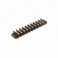
CONN BARRIER BLOCK .563" 10 POS
Manufacturer
Cinch Connectors
Series
142r
Type
Wire to Boardr
Specifications of 10-142
Terminal Block Type
Barrier Block
Number Of Circuits
10
Number Of Positions
20
Pitch
0.563" (14.30mm)
Number Of Rows
2
Current
30A
Voltage
250V
Wire Gauge
10 AWG
Mounting Type
Chassis Mount or Panel Mount
Top Termination
Screws
Bottom Termination
Closed
Barrier Type
2 Wall (Dual)
Features
Flange
Color
Black
Operating Temperature
-55°F ~ 300°F
Material - Insulation
Phenol Formaldehyde (Phenolic)
Material Flammability Rating
UL94 V-1
Product
Barrier Terminal Blocks
Number Of Positions / Contacts
10
Current Rating
30 A
Voltage Rating
250 V
Wire Gauge Max (awg)
10
Lead Free Status / RoHS Status
Lead free / RoHS Compliant
Lead Free Status / RoHS Status
Lead free / RoHS Compliant, Lead free / RoHS Compliant
Other names
10-142-P
10142
CBB310
10142
CBB310


The unique construction of the CIN::APSE contact
provides superior mechanical and electrical performance.
It is constructed of randomly wound molybdenum wire that
is formed into a cyclindrical shape. Standard CIN::APSE
contact diameters are 0.020" and 0.040".
Mechanical
• Small form factor (0.020" diameter by 0.32" min. high)
• Low compression force (approx. 2.5 oz. min. per contact)
• Multiple beam structures
• Several points of contact per button
• Extremely lightweight
• Natural wiping action
Electrical
• Short signal path
• Very low inductance and resistance
• Signal integrity tested in the GHz range
The basic button contact
configuration consists of a single
button installed in our patented
“hourglass” design.
The hourglass cavity retains the
CIN::APSE contact securely.
Typically 0.003" protrudes from the
top and the bottom of the insulator.
CIN::APSE
High-Speed Interconnect Technology
THE BUTTON CONTACT
CIN::APSE APPLIED
®
Step 1:
Using alignment features,
position the CIN::APSE
connector between a LGA chip
package and PCB or two PCBs
that have matching footprints.
1-2
Typical CIN::APSE Applications
• LGA package I/O to PC board (IC packages,
• PC board to PC board (parallel processors,
• Flex circuit to PC board (rigid flex, harnessing)
• Flex circuit to ceramic (chip to harness)
multi-chip modules)
enhancement/mezzanine cards)
Step 2:
Add Z-Axis compression
and secure.
Call Toll Free: 1 (800) 323-9612
Related parts for 10-142
Image
Part Number
Description
Manufacturer
Datasheet
Request
R

Part Number:
Description:
CONN BARRIER BLOCK .438" 10 POS
Manufacturer:
Cinch Connectors
Datasheet:

Part Number:
Description:
CONN BARRIER BLOCK .375" 10 POS
Manufacturer:
Cinch Connectors
Datasheet:

Part Number:
Description:
CONN BARRIER BLOCK .375" 10 POS
Manufacturer:
Cinch Connectors
Datasheet:

Part Number:
Description:
TERMINAL BLOCK JUMPER TYPE F
Manufacturer:
Cinch Connectors
Datasheet:

Part Number:
Description:
D-Subminiature Connectors MCHNED PIN 20-24AWG
Manufacturer:
Cinch Connectors
Datasheet:
Part Number:
Description:
Terminal Block,4 Contacts,0.44 Pitch
Manufacturer:
Cinch Connectors
Datasheet:

Part Number:
Description:
Terminal Block,8 Contacts,0.375 Pitch
Manufacturer:
Cinch Connectors
Datasheet: