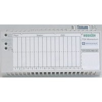
490NAD91105 SQUARE D, 490NAD91105 Datasheet - Page 45

490NAD91105
Manufacturer Part Number
490NAD91105
Description
PROFIBUS PLC CONNECTOR, RECEPTACLE, 9POS
Manufacturer
SQUARE D
Series
NADr
Datasheet
1.170BNO67100.pdf
(108 pages)
Specifications of 490NAD91105
Connector Type
PLC
Gender
Plug
No. Of Contacts
9
Connector Mounting
Cable
For Use With
Square D Advantys STB Distributed I/OSystem
Lead Free Status / RoHS Status
Lead free / RoHS Compliant
Characteristics
Range
Number of channels
Output nominal
values
Output logic
Voltage limits
Response time
Switching capability
Relay contact life
Swapping
Isolation
Output surge protection (internal)
Leakage current (at state 0)
Maximum surge current per relay/channel
Minimum load current
Fallback on
COM fault
Reset on COM fault
I/O base
PDM power
distribution module
Logic bus current consumption c 5 V
Characteristics of AC and relay output modules
Type of module
Voltage
Current per channel/contact
Default
User-configurable setting (2)
Permanent
Absolute maximum
Off-to-on
On-to-off
Mechanical
Electrical
Cold swap
Hot swap
Between channels and logic bus V
Channel to channel
Logic bus to actuator bus
Default state
User-configurable (2)
Default state
User-configurable (2)
Coil voltage
Model
Coil protection
(continued)
V
A
V
V
VA
V
V
mA
A
mA
V
mA
Advantys
Solution
Alternating current and relay digital output
modules
(1) For greater protection, an RC circuit, a free-wheel diode or a GMOV peak limiter circuit
(2) Requires configuration software Advantys STP SPU 1
STB DRC 3210
Standard
2 “NO/NC”
c 24, a 115/230
2 at c 24 V
2 at a 230 V
Positive on both channels
Positive or negative by channel
c 5...30, a 20...250
–
5.25 ms
6.75 ms
600 (resistive load)
10
10
and current)
Yes
Yes, depending on NIM and mandatory nature of module. See table on page 41
a 1780 for 1 minute
a 500 for 1 minute
c 1500 for 1 minute
Yes, by GMOV (300 V rms, c 385 V,
400 Joules max. for 20 µs, 0.1 W max.) (1)
–
Capacitive load of 20 at t = 10 ms
50
2 coils de-energized
Fallback state: hold last value or set to predefined value (0 or 1) on each channel individually.
Manual reset by user required
–
STB XBA 2000
c 24
STB PDT 3100/3105
10 A time-lag fuse on PDM
60
appropriate to the voltage should be mounted in parallel across the terminals of each actuator.
6
5
operations
operations (resistive load at max. voltage
STB DRA 3290
2 “NO” and “NC”
7 at c 24 V
7 at a 230 V
10 ms
10 ms
2100 (resistive load)
STB XBA 3000
70
™
STB Distributed I/O
STB DAO 5260
2
a 115
2 at 30°C (86°F)
1 at 60°C (140°F)
a 74...132
a 132
0.5 period a
0.5 period a
–
–
–
a 1780 for 1 minute
–
External 5 A fuse
required
2 at a 132 V max.
30 over 1 period
20 over 2 periods
1
0 on both channels
Manual or automatic resetting
STB XBA 2000
–
STB PDT 2100/2105
–
ppp
.
STB DAO 8210
a 115/230
a 20...265
a 300 for 10 s
a 400 for 1 cycle
10 ms
10.5 ms
–
Transient voltage by
varistor and RC.
2.5 at a 230 V
2 at a 115 V
5
45
0


