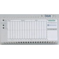
490NAD91105 SQUARE D, 490NAD91105 Datasheet - Page 56
490NAD91105
Manufacturer Part Number
490NAD91105
Description
PROFIBUS PLC CONNECTOR, RECEPTACLE, 9POS
Manufacturer
SQUARE D
Series
NADr
Datasheet
1.170BNO67100.pdf
(108 pages)
Specifications of 490NAD91105
Connector Type
PLC
Gender
Plug
No. Of Contacts
9
Connector Mounting
Cable
For Use With
Square D Advantys STB Distributed I/OSystem
Lead Free Status / RoHS Status
Lead free / RoHS Compliant


Presentation,
description
56
2
1
3
4
5
6
Advantys
Solution
Analog input/output modules
The STB analog inputs allow the acquisition of various analog values encountered in
industrial applications. The STB analog outputs are used to control analog field
devices such as variable speed drives, proportional control valves, etc.
The range of basic analog I/O modules comprises:
b 3 analog input modules:
v 2 analog voltage input channels 0…10 V,
v 2 analog current input channels ± 10 V,
v 2 analog current input channels 4...20 mA.
b 3 analog output modules:
v 2 analog channels, current output 0...10 V,
v 2 analog channels, current output ± 10 V,
v 2 analog channels, voltage output 4...20 mA.
The range of standard analog I/O modules comprises:
b 5 analog input modules:
v 2 analog voltage input channels ± 10 V,
v 2 analog current input channels 0...20 mA,
v 2 channels for thermocouple, temperature probe or voltage (mV),
v 4 analog input channels 15 bits + sign, current 4...20 mA and 0...20 mA,
v 4 analog input channels 15 bits + sign, current 4...20 mA and 0...20 mA, HART
tolerant.
b 3 analog output modules:
v 2 analog channels, current output 0...10 V or ± 10 V,
v 2 analog channels, current output 0...20 mA,
v 2 analog channels, output current 4...20 mA and 0...20 mA, 15 bits + sign.
The front panel of a typical analog input/output module features:
1
2
Indication
Module status (1)
Module error (2)
3
4
To be ordered separately:
b An STB XBA 1000 mounting base, width 13.9 mm (0.54").
Removable connectors (6 contacts), screw-type STB XTS 1100 or spring-type
STB XTS 2100.
b Grounding of cable shielding is mandatory. The optional grounding kit
STB XSP 3000 can also be used to secure cables in installations subject
to severe vibration.
5
6
Optional mechanical keying pins:
v between I/O module and I/O base: STB XMP 7700,
v between wiring connectors and I/O module: STB XMP 7800.
These devices ensure that the I/O modules, their bases and the wiring connectors
are properly matched after dismantling or replacement.
b Sheets of customizing labels: STB XMP 7600.
(1) RDY LED lit: module OK. RDY LED off: no power from PDM. RDY LED flashing: fault.
(2) ERR LED lit: internal error ERR LED off: module OK. ERR LED flashing: module error.
Presentation
Description
A place for a customized label.
A display showing the state of the module (RDY, ERR).
A color-coded module identification stripe.
Two receptacles for screw or spring-type removable connectors.
Optional grounding kit STB XSP 3000.
Connectors STB XSP 3010 for cables with cross-section 1.5…6 mm
0.23"
(1.19...0.43"
Consult the
STB SUS 8800 or available from our website www.us.telemecanique.com.
2
) or STB XSP 3020 for cables with cross-section 5…11 mm
“
System hardware components reference guide
2
).
™
STB Distributed I/O
Basic analog
I/O modules
Green RDY LED
–
”
included on the CD-ROM
Standard analog
I/O modules
Green RDY LED
Red ERR LED
2
2
(0.06 ...
0