MKT1826322014 Vishay, MKT1826322014 Datasheet - Page 10
MKT1826322014
Manufacturer Part Number
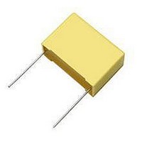
MKT1826322014
Description
CAPACITOR POLYESTER 0.022UF, 100V, RADIAL
Manufacturer
Vishay
Series
MKT1826r
Datasheet
1.MKT1826247014.pdf
(18 pages)
Specifications of MKT1826322014
Capacitor Application
Safety / Suppression
Capacitor Dielectric Type
Polyester
Capacitance Tolerance
± 5%
Voltage Rating
100VDC
Capacitor Case Style
Radial Leaded
Capacitance
0.022µF
Tolerance
5 %
Termination Style
Radial
Dimensions
2.5 mm W x 7.2 mm L x 6.5 mm H
Lead Spacing
5 mm
Operating Temperature Range
- 55 C to + 125 C
Product
Metallized Polyester Film Capacitors
Lead Free Status / RoHS Status
Lead free / RoHS Compliant


GENERAL
All film capacitors listed in this catalog are manufactured in
plants that have been certified to ISO 9001/ISO 9002
(EN 29001/EN 29002).
ISO 9001 is a comprehensive quality system that comprises
all activities of development, material procurement, production,
quality assurance and customer service. It is based on national
and international standards such as DIN CECC and IEC. All
quality and manufacturing procedures are described in detail
in the Quality Manual of the company.
Modern quality tools such as SPC, FMEA, Zero-Defect quality
programs and Q-Audits serve for the continued improvement
of quality. Constant training programs make sure that all people
involved in the entire process will be kept up to date with the
latest production and quality procedures, thus meeting our
customers requirements.
The following quality terms are alphabetically sorted.
AQL
The Acceptable Quality Level represents the failure share in
the test lot for all sampling instructions of a sampling plan to
which a high acceptance probability is assigned. The AQL is
expressed as the number of faulty components in relation to
100 components.
The sampling inspection is carried out by means of a samp-
ling plan according to DIN ISO 2859 part 1 (identical to
MIL STD 105 or IEC 60410) and is used to evaluate the test
lot.
BATH TUBE CURVE
It represents the characteristic shape of the failure rate over
the operation period. Its course may be divided into three time
phases:
The failure rate at phase II can be assumed to be constant.
BURN-IN
The burn-in or artificial aging of components is a measure
to minimize early failure rates. In the burn-in test the
components are generally subjected to an electrical and
thermal stress.
General Technical Information
Vishay Roederstein
www.vishay.com
12
III. Wear-out phase:
II. Application phase:
I. Early failure phase:
λ
Early Failures
|
Constant Failure Rate
||
Wear Out Failures
For technical questions, contact dc-film@vishay.com
|||
Film Capacitors
t
CPK
Assuming a stable and normally distributed process, the
process capability factor (C
the process versus the tolerance limiting values.
A process is considered to be:
FAILURE
A failure means the unacceptable deviation from at least one
property of a component that was without a defect at the be-
ginning of its application. There are critical failures (e.g. short
or open circuit) and failures caused by exceeding limiting
values.
In case of claims the following information will be required by
the manufacturer:
This information will allow the manufacturer to solve the
problem as quick as possible and to initiate the appropriate
corrective actions.
FAILURE RATE (λ λ λ λ λ )
The failure rate is expressed in “fit” (failures in time) and indi-
cates the number of failures per 10
The calculations of the failure rates are based on
CEI IEC 601709. The fit ratings provided in this catalog refer
to 40°C, 0.5 x U
(The smallest C
x
LSL = Lower specification limit
USL = Upper specification limit
s
Bad if
Acceptable if
Good if
Excellent if
• Kind of defect observed
• Occurrence of the defect (e.g. incoming inspection, burn
• Operating conditions
• Date code (on the component)
• Number of pieces rejected
• Lot size
• Lot number (on the label of the box)
• Return defect samples for failure analysis
1 fit = 1 x 10
N = Number of components tested
n = Number of failures
t
in, reliability test, field)
b
= Test time in hours
= Arithmetic mean value
= Standard deviation
C
PK
λ
ref
= ———— or ————
-9
= ———— [fit]
R
/ h (1 failure per 10
x - LSL
PK
and an upper confidence level of 60%.
-value is valid)
3s
N*
n
C
C
C
C
t
b
PK
PK
PK
PK
< 1.33
≥ 1.33
≥ 1.67
≥ 2.00
PK
) indicates the consistency of
USL - x
3s
9
9
component test hours.
component hours)
Document Number 26033
Revision 01-Dec-03
Related parts for MKT1826322014
Image
Part Number
Description
Manufacturer
Datasheet
Request
R

Part Number:
Description:
357-036-542-201 CARDEDGE 36POS DL .156 BLK LOPRO
Manufacturer:
Vishay
Datasheet:
Part Number:
Description:
357-036-542-201 CARDEDGE 36POS DL .156 BLK LOPRO
Manufacturer:
Vishay
Datasheet:
Part Number:
Description:
357-036-542-201 CARDEDGE 36POS DL .156 BLK LOPRO
Manufacturer:
Vishay
Datasheet:
Part Number:
Description:
357-036-542-201 CARDEDGE 36POS DL .156 BLK LOPRO
Manufacturer:
Vishay
Datasheet:
Part Number:
Description:
357-036-542-201 CARDEDGE 36POS DL .156 BLK LOPRO
Manufacturer:
Vishay
Datasheet:
Part Number:
Description:
357-036-542-201 CARDEDGE 36POS DL .156 BLK LOPRO
Manufacturer:
Vishay
Datasheet:
Part Number:
Description:
357-036-542-201 CARDEDGE 36POS DL .156 BLK LOPRO
Manufacturer:
Vishay
Datasheet:
Part Number:
Description:
357-036-542-201 CARDEDGE 36POS DL .156 BLK LOPRO
Manufacturer:
Vishay
Datasheet:
Part Number:
Description:
357-036-542-201 CARDEDGE 36POS DL .156 BLK LOPRO
Manufacturer:
Vishay
Datasheet:
Part Number:
Description:
357-036-542-201 CARDEDGE 36POS DL .156 BLK LOPRO
Manufacturer:
Vishay
Datasheet:
Part Number:
Description:
357-036-542-201 CARDEDGE 36POS DL .156 BLK LOPRO
Manufacturer:
Vishay
Datasheet:
Part Number:
Description:
357-036-542-201 CARDEDGE 36POS DL .156 BLK LOPRO
Manufacturer:
Vishay
Datasheet:
Part Number:
Description:
357-036-542-201 CARDEDGE 36POS DL .156 BLK LOPRO
Manufacturer:
Vishay
Datasheet:
Part Number:
Description:
357-036-542-201 CARDEDGE 36POS DL .156 BLK LOPRO
Manufacturer:
Vishay
Datasheet:
Part Number:
Description:
357-036-542-201 CARDEDGE 36POS DL .156 BLK LOPRO
Manufacturer:
Vishay
Datasheet: