MKT1826322014 Vishay, MKT1826322014 Datasheet - Page 5
MKT1826322014
Manufacturer Part Number
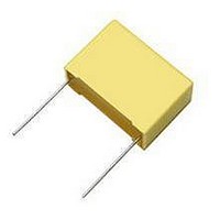
MKT1826322014
Description
CAPACITOR POLYESTER 0.022UF, 100V, RADIAL
Manufacturer
Vishay
Series
MKT1826r
Datasheet
1.MKT1826247014.pdf
(18 pages)
Specifications of MKT1826322014
Capacitor Application
Safety / Suppression
Capacitor Dielectric Type
Polyester
Capacitance Tolerance
± 5%
Voltage Rating
100VDC
Capacitor Case Style
Radial Leaded
Capacitance
0.022µF
Tolerance
5 %
Termination Style
Radial
Dimensions
2.5 mm W x 7.2 mm L x 6.5 mm H
Lead Spacing
5 mm
Operating Temperature Range
- 55 C to + 125 C
Product
Metallized Polyester Film Capacitors
Lead Free Status / RoHS Status
Lead free / RoHS Compliant


DIELECTRIC PROPERTIES (TYPICAL VALUES)
PET = Polyethylene Terephthalate (Polyester), PP = Polypropylene, PC = Polycarbonate.
DEFINITIONS
The following definitions apply to both film/foil capacitors and
metallized film capacitors.
RATED VOLTAGE (U
The rated voltage is the voltage for which the capacitor is
designed. It is defined as the maximum DC or AC (RMS) volt-
age or the pulse voltage that may continuously be applied to
the terminals of a capacitor up to an operating temperature of
+ 85°C. The rated voltage is dependent upon the property of
the dielectric material, the film thickness and the operating
temperature.
Above + 85°C, but without exceeding the maximum
temperature, the rated voltage has to be derated in
accordance to the dielectric material used. For details, please
refer to the individual data sheets of this catalog.
TEST VOLTAGE OR DIELECTRIC STRENGTH
The test voltage of a capacitor is higher than the rated DC
voltage and may only be applied for a limited time.
The dielectric strength is measured between the electrodes
with a test voltage of 1.6 x U
of 2.0 x U
two seconds.
The occurrence of self-healing or clearing-effects during the
application of the test voltage is permitted for metallized film
capacitors.
AC VOLTAGE
The AC voltage ratings in this catalog refer to clean
sinusoidal voltages without transients. The capacitors in this
catalog must not, therefore, be operated in mains applications
(e.g. across the line). This applies also to capacitors that are
rated with AC voltages ≥ 250 VAC.
Capacitors especially designed for mains operations ( X- and
Y-Capacitors) are listed in our catalog “RFI Suppression Ca-
pacitors”. For operations in the higher frequency range the
applied AC voltage has to be derated. The derated AC volt-
ages are provided in the graphs “Permissible AC Voltage Ver-
sus Frequency” of this catalog.
The calculations of the graphs are based on the assumption
that the temperature rise measured on the surface of the ca-
pacitor under working conditions do not exceed 10°C.
Document Number 26033
Revision 01-Dec-03
PARAMETER
Relative Dielectric Constant
DF at 1kHz (tan δ in %)
IR (Megohm x µF)
Dielectric Absorption (%)
Capacitance Drift ∆C/C (%)
Moisture Absorption (%)
Maximum Temperature (°C)
TC (ppm/°C)
R
at film/foil capacitors. The time applied is typically
R
)
R
at metallized film capacitors and
For technical questions, contact dc-film@vishay.com
+ 400, ± 200
25,000
PET
125
3.2
0.5
0.2
1.5
0.4
Film Capacitors
SUPERIMPOSED AC VOLTAGE
When an AC voltage is superimposed to a DC voltage, the
sum of both the DC voltage (U
AC voltage (U
of the capacitor.
PULSE VOLTAGE
The RMS value of a pulse voltage [U
ceed the rated AC voltage U
The peak value of the pulse voltage (U
the rated DC voltage.
For critical applications, please forward your voltage
and current waveforms (worst case conditions) for our
type proposal.
Pd
U
f
C
tan δ = Dissipation factor at frequency (f)
∆ϑ
β
d
A
α
General Technical Information
RMS
Pd = U
- 200, ± 100
= Dissipation Power (mW)
= Applied RMS-Voltage (V)
= Frequency (Hz)
= Capacitance (F)
= Temperature rise caused by the working
= Heat dissipation coefficient of the lead
= Lead wire diameter (mm)
= Surface of the capacitor body (cm
= Heat transfer coeff. [mW/(°C*cm
100,000
0.02
0.05
0.01
100
(For non-sinusoidal voltages the tan δ
corresponding to the frequency with the
steepest voltage gradient is to be applied)
conditions (°C)
wire material [mW/(°C*mm)] (β = 7.9 for Cu)
(α = 0.96 for plastic boxes with a smooth surface)
PP
2.2
0.5
RMS
PK
) must not exceed the rated DC voltage [U
∆ϑ = ——————— (°C)
2
* 2 * π * f * C * tan δ * 1000 (mW)
U
U
R(DC)
R(AC)
U
d * β + A * α
R(DC)
≥ U
≥ U
Pd
R(AC)
RMS(pulse)
≥ U
DC
Vishay Roederstein
DC
+ U
PK
.
) and the peak value of the
PK
RMS(pulse)
PK
0, ± 100
25,000
) must not exceed
125
2.8
0.1
0.1
1.0
0.3
PC
2
)]
2
www.vishay.com
)
] must not ex-
R(DC)
7
]
Related parts for MKT1826322014
Image
Part Number
Description
Manufacturer
Datasheet
Request
R

Part Number:
Description:
357-036-542-201 CARDEDGE 36POS DL .156 BLK LOPRO
Manufacturer:
Vishay
Datasheet:
Part Number:
Description:
357-036-542-201 CARDEDGE 36POS DL .156 BLK LOPRO
Manufacturer:
Vishay
Datasheet:
Part Number:
Description:
357-036-542-201 CARDEDGE 36POS DL .156 BLK LOPRO
Manufacturer:
Vishay
Datasheet:
Part Number:
Description:
357-036-542-201 CARDEDGE 36POS DL .156 BLK LOPRO
Manufacturer:
Vishay
Datasheet:
Part Number:
Description:
357-036-542-201 CARDEDGE 36POS DL .156 BLK LOPRO
Manufacturer:
Vishay
Datasheet:
Part Number:
Description:
357-036-542-201 CARDEDGE 36POS DL .156 BLK LOPRO
Manufacturer:
Vishay
Datasheet:
Part Number:
Description:
357-036-542-201 CARDEDGE 36POS DL .156 BLK LOPRO
Manufacturer:
Vishay
Datasheet:
Part Number:
Description:
357-036-542-201 CARDEDGE 36POS DL .156 BLK LOPRO
Manufacturer:
Vishay
Datasheet:
Part Number:
Description:
357-036-542-201 CARDEDGE 36POS DL .156 BLK LOPRO
Manufacturer:
Vishay
Datasheet:
Part Number:
Description:
357-036-542-201 CARDEDGE 36POS DL .156 BLK LOPRO
Manufacturer:
Vishay
Datasheet:
Part Number:
Description:
357-036-542-201 CARDEDGE 36POS DL .156 BLK LOPRO
Manufacturer:
Vishay
Datasheet:
Part Number:
Description:
357-036-542-201 CARDEDGE 36POS DL .156 BLK LOPRO
Manufacturer:
Vishay
Datasheet:
Part Number:
Description:
357-036-542-201 CARDEDGE 36POS DL .156 BLK LOPRO
Manufacturer:
Vishay
Datasheet:
Part Number:
Description:
357-036-542-201 CARDEDGE 36POS DL .156 BLK LOPRO
Manufacturer:
Vishay
Datasheet:
Part Number:
Description:
357-036-542-201 CARDEDGE 36POS DL .156 BLK LOPRO
Manufacturer:
Vishay
Datasheet: