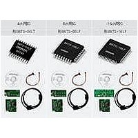
B6TS-04LT Omron, B6TS-04LT Datasheet - Page 15

B6TS-04LT
Manufacturer Part Number
B6TS-04LT
Description
Capacitance Touch Sensors Sensing IC
Manufacturer
Omron
Series
-r
Type
Capacitiver
Specifications of B6TS-04LT
Sensitivity
-
Response Time
-
Interface
SPI
Channel Inputs
4 Key
Voltage - Supply
3 V ~ 5 V
Actuator Type
-
Package / Case
20-LSSOP (0.173", 4.40mm Width)
Lead Free Status / RoHS Status
Lead free / RoHS Compliant
6.2.11
6.2.12
6.2.13 ROMSTR: EEPROM write (only write is enabled in setup mode)
6.2.14 REFx: Reference value for each channel (read/write enabled only in setup mode)
Command code
Command code
Command code
Command code
0x40..0x4F D15 D14 D13 D12 D11 D10 D9
0x3D 1
0x3E TS TER
0x3F 0
SLP: Sleep time (read/write enabled only in setup mode)
MODE: Operation mode (read/write enabled only in setup mode)
TS: Teaching start
TER: Teaching error flag
DC: Drift correction
CHG: CHG pin function
CON: Output setting
EEPROM built in this chip.
possible to change the operation mode.
correction or the like.
Sets the standby time between one measurement and the next measurement (sleep time).
Sleep continues for SOP value×10mS (typ)
When SLP is set to “0”, measurements are made consecutively without sleep time.
Only lower-order 8 bits are valid. If the other bits are written, they are ignored.
Sets various modes.
Only the bits described are valid.
If the other bits are written, they are ignored.
When this command is issued by setting the data to 0x5354, all the parameter data are written in the
When the data is other than 0x5354, this command is ignored.
Until this command is issued, received write data are stored in volatile memory.
While data is being written in EEPROM, the CHG pin is low.
Also, during the write, inputs to the /SETUP and MEAS pins are ignored. Accordingly, it is not
The reference value for each channel can be set with an unsigned 16-bit integer.
Users can alter this setting (in setup mode), or rewrite it by teaching. It cannot be changed by drift
15
15
15
15
14
14
14
14
1
1
Teaching mode is entered when “1” is written in this bit.
(During read out this bit is always “0”)
Set/reset according to result of teaching.
Set to “1” when teaching finishes normally.
If a teaching error occurs, this bit is set to “0”.
This flag is not cleared automatically. To clear this flag, write “1” to this bit.
Sets whether or not to execute drift correction.
1: Drift correction executed, 2: Not executed
The signal is specified from the CHG pin in normal measurement mode (serial communication
mode). With this pin set to “1”, when on/off changes in any channel (when any channel is
touched (comes on) or changes from touch to no-touch (goes off)), the signal is high.
When this pin is set to “0”, the signal is high every time a measurement finishes.
Sets output mode in normal measurement mode.
When set to “1”, on/off output mode is entered.
When set to “0”, serial communication mode is entered.
13
13
13
13
1
1
0
12
12
12
12
1
1
1
11
11
11
11
1
1
0
10
10
10
10
1
1
0
1
1
1
9
9
9
9
D8
1
1
1
8
8
8
8
D7
D7
1
0
7
7
7
7
D6 D5 D4 D3 D2 D1 D0
D6 D5 D4 D3 D2 D1 D0
1
1
6
6
6
6
1
0
5
5
5
5
1
1
4
4
4
4
1
0
3
3
3
3
DC CHG CON
2
1
2
2
2
0
1
1
1
1
0
0
0
0
0


