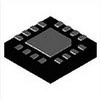
MAX17149ETE+ Maxim Integrated Products, MAX17149ETE+ Datasheet - Page 12

MAX17149ETE+
Manufacturer Part Number
MAX17149ETE+
Description
LED Drivers 6-String WLED Driver
Manufacturer
Maxim Integrated Products
Datasheet
1.MAX17129ETE.pdf
(20 pages)
Specifications of MAX17149ETE+
Operating Supply Voltage
3 V to 26 V
Maximum Supply Current
4 mA
Maximum Power Dissipation
1176 mW
Maximum Operating Temperature
+ 85 C
Mounting Style
SMD/SMT
Package / Case
TQFN-16
Minimum Operating Temperature
- 40 C
Lead Free Status / RoHS Status
Lead free / RoHS Compliant
Low-Cost, 6-String WLED Drivers with
Quick-PWM Step-Up Converter
The MAX17129/MAX17149 are high-efficiency drivers for
arrays of white LEDs. They contain a Quick-PWM step-up
controller, a 3.8V linear regulator, PWM dimming control
circuit, internal power MOSFET, and six regulated current
sources. Figure 2 shows the devices' functional diagram.
When enabled, the step-up controller boosts the output
voltage to provide sufficient headroom for the current
sources to regulate their respective string currents. The
devices feature adjustable pseudo-fixed frequency,
which allows trade-offs between external component
size and operating efficiency.
Both devices have a wide input voltage range, from 6V
to 26V; when IN and V
extended to the 3V to 5.5V range.
The devices implement a PWM dimming brightness con-
trols method, which controls the LED brightness directly
by adjusting the frequency and duty cycle of the square-
wave signal applied on the BRT pin.
The devices have multiple features to protect the control-
ler from faulty conditions. A separate feedback loop lim-
its the output voltage in all circumstances. The devices
monitor each FB_ voltage during the operation. If one or
more strings are open, the corresponding FB_ voltages
are pulled below 600mV (max) and the OVP output is
forced to increase over the overvoltage (40.8 typ) thresh-
old; once the open fault is detected, the respective cur-
rent sources are so disabled. When one or more LEDs
are shorted and the related FB_ voltage exceeds 8V,
short fault is detected and the respective current source
is disabled. When in LED open or short conditions, only
the faulty string is disabled while other strings can still
operate normally.
The devices also feature other kinds of fault protections,
which are overcurrent, output overvoltage, and thermal
shutdown. The cycle-by-cycle current limit is to provide
consistent operation and soft-start protection; when in
overcurrent condition, the devices latch off after a 320Fs
overcurrent fault timer expires. An output overvoltage
protection prevents the devices from switching when the
output exceeds a threshold voltage; A thermal-shutdown
circuit prevents the devices from excessive power dis-
sipation.
12
CC
Detailed Description
are tied together, the range is
The step-up converter is a Quick-PWM type for good
performance. The Quick-PWM control architecture is
a pseudo-fixed-frequency, constant-off-time, current-
mode regulator. The control algorithm is simple: the
internal switch off-time is determined solely by a one-
shot whose period is inversely proportional to output volt-
age, and directly proportional to input voltage. Figure 4
shows the functional diagram with Quick-PWM control
architecture. The off-time one-shot triggers when the
error comparator goes low, the inductor current is below
the current-limit threshold, and the minimum on-time
one-shot times out.
Once the step-up starts up, the output voltage is regu-
lated by selecting the minimum FB voltage between the
detected active current-balancer outputs and compar-
ing it to the OVP divider. The soft-start mechanism is
inserted to provide a controlled current profile during
step-up startup phases.
The Quick-PWM core contains a fast, low-jitter, adjust-
able one-shot that sets the internal MOSFETs off-time.
The one-shot varies the off-time in response to the input
and feedback voltages. The internal switch off-time is
inversely proportional to the output voltage (V
proportional to the input voltage (V
where the switching period (K) is set by the FSEL pin.
This algorithm results in a nearly constant switching
frequency and balanced inductor currents despite the
lack of a fixed-frequency clock generator. The benefits
of a near-constant switching frequency are two-fold: first,
the frequency can be selected to avoid noise-sensitive
regions; second, the inductor ripple-current operating
point remains relatively constant, resulting in easy design
methodology and predictable output-voltage ripple. The
off-time one-shots have good accuracy at the operating
points specified in the Electrical Characteristics table.
Off-times translate only roughly to switching frequencies.
The off-times guaranteed in the Electrical Characteristics
table are influenced by internal switching delays. Resistive
losses, including the inductor, internal MOSFET, the for-
ward voltage of the output diode, output capacitor ESR,
and PCB copper losses in the output and ground tend to
raise the switching frequency at higher output currents.
Quick-PWM Step-Up Controller
T
OFF
=
V
OVP
V
IN
×
IN
K
Off-Time One-Shot
):
OVP
), and


