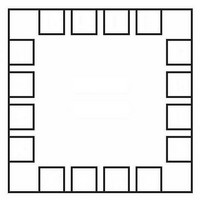
LDS8846003T2 Leadis Technology, LDS8846003T2 Datasheet - Page 6

LDS8846003T2
Manufacturer Part Number
LDS8846003T2
Description
LED Drivers 4Ch no Chrg Pump,4x4 comp to RT9360,SC604
Manufacturer
Leadis Technology
Datasheet
1.LDS8846003T2.pdf
(12 pages)
Specifications of LDS8846003T2
Number Of Segments
4
Operating Supply Voltage
2.7 V to 5.5 V
Maximum Operating Temperature
+ 85 C
Mounting Style
SMD/SMT
Package / Case
TQFN EP
Minimum Operating Temperature
- 40 C
Lead Free Status / RoHS Status
Lead free / RoHS Compliant
LDS8846
BLOCK DIAGRAM
BASIC OPERATION
The device starts operating if the EN pin is set logic
HIGH and input voltage is higher that under voltage
protection lockout threshold.
The low dropout PowerLite™ Current regulator
performs well at input voltages up to 50 mV greater
than the LED forward voltage significantly increasing
the driver’s efficiency.
Input pins EN, CTRL0, CTRL1, and CTRL2 may be
either logic LOW or HIGH during power-up. However,
logic voltage should never exceed input voltage V
and these pins should not be left float.
LED Current Setting
The desired current value in each of the four LED is
set by external resitor R
pin and ground..
The LED current is 400 times greater than the current
through R
following equation:
its resistance in kohms.
R
table below.
© 2008 Leadis Technology
Characteristics subject to change without notice
I
SET
LED
value for typical I
400
SET
x
V
R
and can be estimated (in mA) by
SET
SET
, where V
LED
SET
current is shown at the
connevted between I
SET
=1.2V, and R
Figure 2. LDS8846 Functional Block Diagram
SET
is
SET
IN
,
6
ILED, mA
5
10
15
20
25
30
The average current value may be decreased using
PWM signal applied to either CTRL0, CTRL1 or
CTRL2
frequiencies in the range from 100 Hz to 5 kHz with
duty cycles from 100% to 1% and from 5 kHz to 30
kHz with duty cycles from 100% to 10%. Modulation
frequiencies
recommended especialy at short duty cycles because
LED flicker may be visible.
If CTRL1 and CTRL2 pins are logic HIGH and PWM
signal applies to CTRL0 pin, then all four LEDS are
dimming synchronously.
If CTRL0 and CTRL2 pins are logic HIGH and PWM
signal applies to CTL1 pin, then LEDs from LED1 to
LED3 are dimming, while LED4 is always off.
pin.
R
96
48
32
24
19.2
16
SET
The
lower
, kΩ Nearest standard 1% value
LDS8846
95.3
47.5
31.6 or 32.4
23.7 or 24.3
19.1
15.8 or 16.2
than
Doc. No. 8846DS, Rev. 1.5
100 Hz
allows
modulation
are
not


