HFBR-7924 Avago Technologies US Inc., HFBR-7924 Datasheet - Page 7
HFBR-7924
Manufacturer Part Number
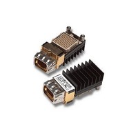
HFBR-7924
Description
Fiber Optic Transmitters, Receivers, Transceivers 4+4 2.7Gbps Pluggabl e Txcvr Module
Manufacturer
Avago Technologies US Inc.
Datasheet
1.HFBR-7924.pdf
(18 pages)
Specifications of HFBR-7924
Function
Pluggable Transceiver, for Parallel Optics
Product
Transceiver
Wavelength
850 nm
Maximum Rise Time
150 ps
Maximum Fall Time
150 ps
Pulse Width Distortion
0.045 ns
Maximum Output Current
25 mA
Operating Supply Voltage
3.135 V to 3.465 V
Maximum Operating Temperature
+ 80 C
Minimum Operating Temperature
0 C
Optical Fiber Type
TX/RX
Data Transfer Rate
2700MBd
Optical Rise Time
0.15ns
Optical Fall Time
0.15ns
Jitter
0.045ns
Operating Temperature Classification
Commercial
Peak Wavelength
850/860nm
Operating Supply Voltage (min)
3.135V
Operating Supply Voltage (typ)
3.3V
Operating Supply Voltage (max)
3.465V
Output Current
25mA
Operating Temp Range
0C to 80C
Mounting
Screw
Pin Count
100
For Use With
Multimode Glass
Lead Free Status / RoHS Status
Lead free / RoHS Compliant


Transmitter Electrical Characteristics
(Over recommended operating conditions: Tc= 0ºC to +80ºC, V cc =3.3V + 5%)
Transmitter Optical Characteristics
(Over recommended operating conditions: Tc= 0ºC to +80ºC, V cc =3.3V + 5%)
Notes:
6. Differential impedance is measured between D
7. The specified optical output power, measured at the output of a 2 meter test cable, will be compliant with IEC 60825-1 Amendment 2,
8. Extinction Ratio is defined as the ratio of the average output optical power of the transmitter in the high (“1”) state to the low (“0”) state
9. These are unfiltered 20% - 80% values measured with a 550 MBd 101010 pattern.
10. Inter-channel Skew is defined for the condition of equal amplitude, zero ps skew input signals.
11. Deterministic Jitter (DJ) is defined as the combination of Duty Cycle Distortion (Pulse-Width Distortion) and Data Dependent Jitter.
12. Total Jitter (TJ) includes Deterministic Jitter and Random Jitter (RJ). Total Jitter is specified at a BER of 10
Parameter
Extinction Ratio
Rise, Fall Time
Inter-channel Skew
Relative Intensity Noise
7
Output Optical Power
50/125 µm, Fiber NA = 0.2
Center Wavelength
Spectral Width - rms
Jitter Contribution
Parameter
Differential Input Impedance
FAULT* Assert time
RESET* Assert time
RESET* De-assert time
Power-On Initiation Time
Control I/Os
Transmit Enable (TX_EN) Assert time
Transmit Enable (TX_EN) De-assert time
Transmit Disable (TX_DIS) Assert time
Transmit Disable (TX_DIS) De-assert time
TX _DIS, TX_EN,
TX_FAULT*,
TX_RESET*
Class 1M Accessible Emission Limits, AEL Regulatory Compliance section.
and is expressed in decibels (dB) by the relationship 10log(P
Deterministic Jitter is measured at the 50% signal threshold level using a 2500 MBd Pseudo Random Bit Sequence of length 2
23), or equivalent, test pattern with zero skew between the differential data input signals.
pattern as for DJ and is measured with all channels operating.
Deterministic
Total
Input Current High
Input Current Low
Output Voltage Low
Output Voltage High
IN
+ and D
P
ER
RIN
DJ
| I
| I
Symbol
s
t
TJ
l
Symbol
Z
T
T
T
T
T
T
T
V
V
r
OUT
, t
in
C
OFF
OFF
ON
ON
OFF
OFF
ON
OL
OH
IH
IL
f
|
|
IN
- over the range 4 MHz to 2 GHz.
high
avg/P
Minimum Typical
-8.0
6
830
Minimum Typical
80
V
2.4
EE
low
avg). The transmitter is driven with a 550 MBd, 101010 pattern.
-4.5
7.5
850
60
50
-127
20
45
100
21
Maximum Unit
-2.0
860
0.85
150
100
-121
50
120
Maximum Unit
120
100
18
18
18
0.5
0.5
0.4
7.5
7.5
7.5
V
CC
-12
nm
nm rms
ps
ps
ps
ps
dBm avg.
dB
dB/Hz
W
µs
µs
ms
ms
µs
µs
ms
ms
mA
mA
V
V
p-p
p-p
for the same 2.5 GBd test
Reference
7
8
9
10
11
12
Reference
6, Figure 9
Figure 13
Figure 14
Figure 14
Figure 15
Figure 15
Figure 15
Figure 15
Figure 17
I
I
2.0 V < V
V
OL
OH
EE
= 4.0 mA
= -0.5 mA
< V
IH
23
< 0.8 V
-1 (PRBS-
IH
< V
CC
Related parts for HFBR-7924
Image
Part Number
Description
Manufacturer
Datasheet
Request
R

Part Number:
Description:
RECEIVER FIBER OPTIC 600NM 5MBD
Manufacturer:
Avago Technologies US Inc.
Datasheet:

Part Number:
Description:
RECEIVER FIBER OPTIC 600NM 40KBD
Manufacturer:
Avago Technologies US Inc.
Datasheet:

Part Number:
Description:
RCVR FIBER OPTIC INTERBUS-S
Manufacturer:
Avago Technologies US Inc.
Datasheet:

Part Number:
Description:
RCVR OPT HI PERF VERS LINK HORZ
Manufacturer:
Avago Technologies US Inc.
Datasheet:
Part Number:
Description:
RCVR OPT HI PERF VERS LINK HORZ
Manufacturer:
Avago Technologies US Inc.
Datasheet:

Part Number:
Description:
XMITTER FIBER OPTIC 600NM 5MBD
Manufacturer:
Avago Technologies US Inc.
Datasheet:

Part Number:
Description:
XMITTER FIBER OPTIC 600NM 40KBD
Manufacturer:
Avago Technologies US Inc.
Datasheet:

Part Number:
Description:
XMITTER FIBER OPTIC HIGH PWR ST
Manufacturer:
Avago Technologies US Inc.
Datasheet:
Part Number:
Description:
XMITTER VERSATILE LINK HORZ
Manufacturer:
Avago Technologies US Inc.
Datasheet:
Part Number:
Description:
XMITTER VERSATILE LINK HORZ
Manufacturer:
Avago Technologies US Inc.
Datasheet:

Part Number:
Description:
XMITTER OPT HI PERFORMANCE VERT
Manufacturer:
Avago Technologies US Inc.
Datasheet:

Part Number:
Description:
Fiber Optic Transmitters, Receivers, Transceivers Versatile Link Horiz
Manufacturer:
Avago Technologies US Inc.
Datasheet:
Part Number:
Description:
Fiber Optic Transmitters, Receivers, Transceivers Versatile Link Horiz
Manufacturer:
Avago Technologies US Inc.
Datasheet:
Part Number:
Description:
Fiber Optic Transmitters, Receivers, Transceivers Versatile Link Horiz
Manufacturer:
Avago Technologies US Inc.
Datasheet:

Part Number:
Description:
FIBER OPTIC TRANSMITTER 660NM
Manufacturer:
Avago Technologies US Inc.
Datasheet: