E3G-L77 Omron, E3G-L77 Datasheet - Page 16
E3G-L77
Manufacturer Part Number
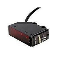
E3G-L77
Description
Photoelectric Sensors - Industrial CONVERGENT 2M DC CONN.
Manufacturer
Omron
Type
Photoelectric Sensorr
Series
E3Gr
Specifications of E3G-L77
Features
Dark ON
Height
68.5 mm
Length
47.8 mm
Maximum Operating Temperature
+ 55 C
Minimum Operating Temperature
- 25 C
Operating Supply Voltage
10 V to 30 V
Width
21 mm
Sensing Distance
2000 mm
Output Configuration
NPN or PNP
Output Current
100mA
Sensor Output
NPN/PNP
Supply Voltage Range Dc
10V To 30V
Sensor Housing
Rectangular
Sensor Input
Optical
Output Type
Transistor
Sensing Range Max
2m
Mounting Type
Bracket
Switch Terminals
Cable
Rohs Compliant
Yes
Sensing Method
Reflective, Diffuse
Sensing Object
Black Paper, Kodak® White Paper
Sensing Light
Infrared
Current - Supply
60mA
Voltage - Supply
10 V ~ 30 V
Package / Case
Module, Connector
Lead Free Status / RoHS Status
Lead free / RoHS Compliant
Lead Free Status / RoHS Status
Lead free / RoHS Compliant, Lead free / RoHS Compliant


Precautions
Do not ignore the following items that are essential for securing
safety during Sensor operation.
•
•
•
J DESIGNING
Load Relay Contact
If E3G is connected to an inductive load with contacts that spark
when the load is turned OFF (e.g., a contactor or valve), the
normally-closed side may be turned ON before the normally-open
side is turned OFF or vice-versa. If both normally-open output
and normally-closed output are used simultaneously, apply an
surge suppressor to the load.
Stabilization on Power-up
The Sensor needs 100 ms to be ready to operate after it is turned
ON. The devices connected to E3G wait until the Sensor is ready
to operate. If the Sensor and load are connected to separate
power supplies, be sure to turn ON the Sensor first.
Power OFF
A single pulse signal may be output from the Sensor immediately
after it is turned OFF. This will occur more frequently if a timer or
counter is connected to the Sensor and power is supplied to the
timer or counter independently. Be sure to supply power to the
timer or counter from the built-in power supply of the Sensor.
Power Supply
If a standard switching regulator is used, be sure to ground the
FG (frame ground) and G (ground) terminals, otherwise the
Sensor may malfunction due to the switching noise of the
regulator.
Repeated Cable Bending
Do not bend the sensor cable repeatedly.
High-tension Lines
Do not wire power lines or high-tension lines alongside the lines
of the Sensor in the same conduit, otherwise the Sensor may be
damaged or may malfunction due to induction. Be sure to wire
the lines of the Sensor separated from power lines or
high-tension lines or laid in an exclusive, shielded conduit.
J WIRING
The E3G has a built-in function to protect the Sensor from load
short-circuiting. If load short-circuiting results, the output will be
turned OFF. In that case, check the wiring and turn ON the E3G
again so that the short-circuit protection circuit will be reset. This
function will operate if the output current flow is at least 2.0 times
the rated load current. If an inductive load is connected to the
E3G, make sure that the inrush current does not exceed 1.2
times the rated load current.
The cable can be extended up to a total length of 100 m, on
condition that the thickness of the wire is at least 0.3 mm.
E3G
Do not use the Sensor in locations with explosive or flam-
mable gas.
Do not use the Sensor in the water or electrically conductive
solutions.
Do not disassemble, repair, or modify the product.
17
•
•
•
•
•
J MOUNTING
Mounting Conditions
If Sensors are mounted face-to-face, make sure that no optical
axes cross each other. Otherwise, mutual interference may
result.
Be sure to install the Sensor carefully so that the directional
angle range of the Sensor will not be directly exposed to
intensive light, such as sunlight, fluorescent light, or incandescent
light.
Do not strike the Photoelectric Sensor with a hammer or any
other tool during the installation of the Sensor, or the Sensor will
loose its water-resistive properties.
Use M4 screws to mount the Sensor.
When mounting the case, make sure that the tightening torque
applied to each screw does not exceed 1.2 N S m.
M12 Connector
Be sure to connect or disconnect the M12 connector after turning
OFF the Sensor.
Be sure to hold the connector cover when connecting or
disconnecting the M12 connector.
The M12 connector must be only hand-tightened.
If the M12 connector is not connected securely, the proper
degree of protection of the Sensor may not be maintained or the
connector may be disconnected due to vibration.
Water Resistance
Do not use the product in water, in rain, or outdoors.
Tighten the operation cover screws and terminal block cover
screws to a torque of 0.3 to 0.5 N S m in order to ensure water
resistivity.
J MAINTENANCE AND INSPECTION
Cleaning
Use only water and mild detergent. Do not use harsh chemicals
or solvents.
J OPERATING ENVIRONMENT
Do not install the E3G in locations with the following conditions.
•
•
•
•
Make sure that the power supply specifications, such as AC
or DC, are correct.
Do not apply voltage or current exceeding the rated ranges.
Do not make mistakes in wiring, such as mistakes in polarity.
Be sure to connect the load correctly.
Do not short-circuit the load terminals.
Excessive dust.
Corrosive gases.
Directly exposed to sprays of water, oil, or chemicals.
Directly exposed to vibration or shock.
E3G
Related parts for E3G-L77
Image
Part Number
Description
Manufacturer
Datasheet
Request
R

Part Number:
Description:
CONVERGENT 50mm PNP CONN.
Manufacturer:
Omron
Datasheet:
Part Number:
Description:
Photoelectric Sensors - Industrial CONVERGENT 200MM PNP CONN
Manufacturer:
Omron
Datasheet:

Part Number:
Description:
Photoelectric Sensors - Industrial NPN/PNP POL RETRORFL
Manufacturer:
Omron
Datasheet:
Part Number:
Description:
Photoelectric Sensors - Industrial RETRO 10M AC/DC TMR. SCREW TERM
Manufacturer:
Omron
Datasheet:

Part Number:
Description:
Photoelectric Sensors - Industrial CONVERGENT 2M AC/DC SCREW TERM
Manufacturer:
Omron
Datasheet:
Part Number:
Description:
Photoelectric Sensors - Industrial RETRO 10M AC/DC SCRE W TERM.
Manufacturer:
Omron
Datasheet:
Part Number:
Description:
Photoelectric Sensors - Industrial Retro 10M DC Connector
Manufacturer:
Omron
Datasheet:
Part Number:
Description:
Photoelectric Sensors - Industrial Retro 10M DC E39-R2 not incl.
Manufacturer:
Omron
Datasheet:
Part Number:
Description:
Photoelectric Sensors - Industrial CONVERGENT 200mm NPN CONN.
Manufacturer:
Omron
Datasheet:
Part Number:
Description:
Photoelectric Sensors - Industrial NPN/PNP DIFF REFLECT
Manufacturer:
Omron
Datasheet:

Part Number:
Description:
G6S-2GLow Signal Relay
Manufacturer:
Omron Corporation
Datasheet:
Part Number:
Description:
Compact, Low-cost, SSR Switching 5 to 20 A
Manufacturer:
Omron Corporation
Datasheet:
Part Number:
Description:
Manufacturer:
Omron Corporation
Datasheet: