E3G-L77 Omron, E3G-L77 Datasheet - Page 9
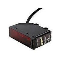
E3G-L77
Manufacturer Part Number
E3G-L77
Description
Photoelectric Sensors - Industrial CONVERGENT 2M DC CONN.
Manufacturer
Omron
Type
Photoelectric Sensorr
Series
E3Gr
Specifications of E3G-L77
Features
Dark ON
Height
68.5 mm
Length
47.8 mm
Maximum Operating Temperature
+ 55 C
Minimum Operating Temperature
- 25 C
Operating Supply Voltage
10 V to 30 V
Width
21 mm
Sensing Distance
2000 mm
Output Configuration
NPN or PNP
Output Current
100mA
Sensor Output
NPN/PNP
Supply Voltage Range Dc
10V To 30V
Sensor Housing
Rectangular
Sensor Input
Optical
Output Type
Transistor
Sensing Range Max
2m
Mounting Type
Bracket
Switch Terminals
Cable
Rohs Compliant
Yes
Sensing Method
Reflective, Diffuse
Sensing Object
Black Paper, Kodak® White Paper
Sensing Light
Infrared
Current - Supply
60mA
Voltage - Supply
10 V ~ 30 V
Package / Case
Module, Connector
Lead Free Status / RoHS Status
Lead free / RoHS Compliant
Lead Free Status / RoHS Status
Lead free / RoHS Compliant, Lead free / RoHS Compliant


E3G
Installation
J POWER SUPPLY
A power supply with full-wave rectification can be connected to
the E3G-MR19(T).
J WIRING
The tensile strength of the cable during operation should not
exceed the values shown below.
J ADJUSTMENTS
Indicators
The following illustration indicates the operation levels of the
E3G.
Set the E3G so that it will work within the stable operation range.
Note: If the operation level is set to the stable operation range,
Part number
E3G-R13, E3G-MR19(T)
E3G-R17
Stable
operation
range
(see note)
Unstable
operation
range
(see note)
Stable
operation
range
(see note)
the E3G will operate with the highest reliability and without
being influenced by temperature change, voltage fluctua-
tion, dust, or setting change. If the operation level cannot
be set to the stable operation range, pay close attention to
environmental changes while operating the E3G.
Operation level
Operation
level x 1.2
Operation
level x 0.8
Stability indicator
(green)
OFF
ON
ON
Tensile strength
50 N max.
10 N max.
Operation indicator (orange)
L. ON
OFF
ON
D. ON
OFF
ON
10
J MOUNTING DIFFUSE MODELS
Mounting Directions
Make sure that the sensing side of the Sensor is parallel with the
surface of each sensing object. Do not tilt the Sensor towards the
sensing object.
If the sensing object has a glossy surface, tilt the Sensor by 5° to
10° as shown below, provided that the Sensor is not influenced
by any background objects.
Glossy object
Sensing side
Surface of sensing object
E3G
Related parts for E3G-L77
Image
Part Number
Description
Manufacturer
Datasheet
Request
R

Part Number:
Description:
CONVERGENT 50mm PNP CONN.
Manufacturer:
Omron
Datasheet:
Part Number:
Description:
Photoelectric Sensors - Industrial CONVERGENT 200MM PNP CONN
Manufacturer:
Omron
Datasheet:

Part Number:
Description:
Photoelectric Sensors - Industrial NPN/PNP POL RETRORFL
Manufacturer:
Omron
Datasheet:
Part Number:
Description:
Photoelectric Sensors - Industrial RETRO 10M AC/DC TMR. SCREW TERM
Manufacturer:
Omron
Datasheet:

Part Number:
Description:
Photoelectric Sensors - Industrial CONVERGENT 2M AC/DC SCREW TERM
Manufacturer:
Omron
Datasheet:
Part Number:
Description:
Photoelectric Sensors - Industrial RETRO 10M AC/DC SCRE W TERM.
Manufacturer:
Omron
Datasheet:
Part Number:
Description:
Photoelectric Sensors - Industrial Retro 10M DC Connector
Manufacturer:
Omron
Datasheet:
Part Number:
Description:
Photoelectric Sensors - Industrial Retro 10M DC E39-R2 not incl.
Manufacturer:
Omron
Datasheet:
Part Number:
Description:
Photoelectric Sensors - Industrial CONVERGENT 200mm NPN CONN.
Manufacturer:
Omron
Datasheet:
Part Number:
Description:
Photoelectric Sensors - Industrial NPN/PNP DIFF REFLECT
Manufacturer:
Omron
Datasheet:

Part Number:
Description:
G6S-2GLow Signal Relay
Manufacturer:
Omron Corporation
Datasheet:
Part Number:
Description:
Compact, Low-cost, SSR Switching 5 to 20 A
Manufacturer:
Omron Corporation
Datasheet:
Part Number:
Description:
Manufacturer:
Omron Corporation
Datasheet: