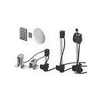
E39-S54 Omron, E39-S54 Datasheet - Page 43

E39-S54
Manufacturer Part Number
E39-S54
Description
Photoelectric Sensors - Industrial Slit Kit
Manufacturer
Omron
Datasheet
1.E39-S53.pdf
(48 pages)
Specifications of E39-S54
Lead Free Status / RoHS Status
Lead free / RoHS Compliant
E3S-A/B
Internal Connection
Note: Pin No. 2 and 4 are connected internally.
External Connections
Precautions
The supplied voltage must be within the rated voltage range. Un-
regulated full-or half-wave rectifiers must not be used as power sup-
plies.
If the input/output lines of the photoelectric sensor are placed in the
same conduit or duct as power lines or high-voltage lines, the photo-
electric sensor could be induced to malfunction, or even be dam-
aged, by electrical noise. Either separate the wiring, or use shielded
lines as input/output lines to the photoelectric sensor.
Do not use a hammer to hit the amplifier when mounting or the am-
plifier will loose watertightness.
Note the following when using the E39-R3, E39-RSA, or E39-RSB
reflector (tape):
For DC
Item
1. Before applying adhesive tape to the reflector, make sure that
2. Do not cut the reflector or the reflector will loose
3. Do not press the reflector with a metal object or a nail, or
Plug (for E3S-A with Connector)
E3S-A/B
NPN Output
PNP Output
the reflector is free from oil or dust, or otherwise the adhesive
tape will not stick to the reflector properly.
watertightness.
otherwise the reflector will not function properly.
Terminal No.
Brown
Black
Blue
Color of
cord
1
4
3
Coonection
pin No.
Plug
Plug
Power supply (+V)
Output
Power supply (0 V)
Output
Output
Brown
Black
Blue
Brown
Black
Blue
Application
Load
Load
Brown
Blue
Black
+ V
0 V
+ V
0 V
Tightening the Plug
Turn part B by hand (do not use a pliers or the plug will be damaged)
and tighten it with part C so that length A is nearly zero. Part B must
be tightened properly with part C, or otherwise part B could be
loosen by vibration and the sensor will not maintain the specified en-
closure ratings.
Note: Use the spacer (sold together) to mount the photoelectric
Position of Optical Axis of Through-beam Model
Unlike conventional through-beam models, the E3S Through-beam
Photoelectric Sensor incorporates 2 lenses. But the lens actually in
use is the one marked with an arrow indicating the position of the
optical axis. When using a slit, attach it to the lens marked with the
arrow.
sensor with or without the enclosed mounting bracket (refer
to Dimensions).
Unused lens
Lens actually in use (attach
the slit to this lens)
(C)
(A)
(B)
Arrow indicating
optical axis po-
sition
E3S-A/B
43


