5536501-1 TE Connectivity, 5536501-1 Datasheet - Page 6
5536501-1
Manufacturer Part Number
5536501-1
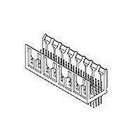
Description
HARD METRIC CONNECTOR, HEADER, 24POS
Manufacturer
TE Connectivity
Type
Backplaner
Series
Z-PACKr
Specifications of 5536501-1
Pitch (mm)
2mm
Gender
HDR
Body Orientation
Straight
Number Of Contact Rows
4
Number Of Contacts
24POS
Termination Method
Solder
Mounting Style
Through Hole
Contact Plating
Gold
Voltage Rating Max
30VAC
Contact Material
Phosphor Bronze
Housing Material
Liquid Cryst Polymer
Product Height (mm)
17mm
Product Depth (mm)
15.8mm
Product Length (mm)
11.88mm
Connector Type
Backplane
Row Pitch
2mm
Pitch Spacing
2mm
No. Of Contacts
24
Contact Termination
Through Hole
No. Of Rows
4
Rohs Compliant
Yes
Number Of Rows
4
Number Of Positions / Contacts
24
Pitch
2 mm
Termination Style
Solder
Product Type
Connector
Pcb Mounting Orientation
Vertical
Post Type
Solder Post
Module Type
Signal
Mating Post Length (mm [in])
6.50 [0.256]
Pin Header Width (mm [in])
16.00 [0.622]
Voltage Rating (vac)
30
Termination Post Length (mm [in])
4.25 [0.167]
Number Of Signal Positions
24
Sequencing
No
Post Plating
Tin
Centerline, Matrix (mm [in])
2.00 x 2.00 [.079 x .079]
Contact Type
Pin
Contact Base Material
Phosphor Bronze
Contact Plating, Mating Area, Material
Gold (30)
Connector Style
Plug
Rohs/elv Compliance
RoHS compliant, ELV compliant
Lead Free Solder Processes
Wave solder capable to 240°C, Wave solder capable to 260°C, Wave solder capable to 265°C, Reflow solder capable to 245°C, Reflow solder capable to 260°C, Pin-in-Paste capable to 245°C, Pin-in-Paste capable to 260°C
Rohs/elv Compliance History
Always was RoHS compliant
Applies To
Printed Circuit Board
Application
Fixed-Board
Lead Free Status / RoHS Status
Compliant


4.2.
4.3.
4.4.
Rev C
B.
Requalification Testing
If changes significantly affecting form, fit or function are made to the product or manufacturing process,
product assurance shall coordinate requalification testing, consisting of all or part of the original testing
sequence as determined by development/product, quality and reliability engineering.
Acceptance
Acceptance is based on verification that the product meets requirements of Figure 1. Failures attributed
to equipment, test setup or operator deficiencies shall not disqualify the product. When product failure
occurs, corrective action shall be taken and samples resubmitted for qualification. Testing to confirm
corrective action is required before resubmittal.
Quality Conformance Inspection
The applicable quality inspection plan will specify the sampling acceptable quality level to be used.
Dimensional and functional requirements shall be in accordance with the applicable product drawing
and this specification.
2.
Test Sequence
Qualification inspection shall be verified by testing samples as specified in Figure 3.
Power connectors.
Power connector housings and contacts shall be prepared in accordance with applicable
Instruction Sheets and shall be selected at random from current production. All test groups
shall consist of 5 connectors each of the largest available size. All tests requiring individual
contact measurements shall be conducted on 30 contacts randomly selected over the 5
connectors. Test groups 1 and 2 shall be mounted on printed circuit boards designed to
accommodate vibration and physical shock fixturing providing a series circuit for all contacts
with access to measure termination resistance.
Contact Resistance Measurement Points
Figure 4
108-1441
6 of 8
Related parts for 5536501-1
Image
Part Number
Description
Manufacturer
Datasheet
Request
R

Part Number:
Description:
Printers THERMAL PRINTER HS-SLEEVE MARKER
Manufacturer:
TE Connectivity


Part Number:
Description:
High Speed / Modular Connectors 30P HEADER ASSY
Manufacturer:
TE Connectivity
Datasheet:

Part Number:
Description:
High Speed / Modular Connectors REC 6X005P R/A LT B-PLANE HS3
Manufacturer:
TE Connectivity
Datasheet:

Part Number:
Description:
High Speed / Modular Connectors 2MM HM RCPT 50P R/A AU
Manufacturer:
TE Connectivity
Datasheet:

Part Number:
Description:
High Speed / Modular Connectors 2MM HM RCPT 50P R/A AU
Manufacturer:
TE Connectivity
Datasheet:


Part Number:
Description:
Manufacturer:
TE Connectivity
Datasheet:


Part Number:
Description:
Manufacturer:
TE Connectivity
Datasheet:

Part Number:
Description:
Manufacturer:
TE Connectivity
Datasheet:

Part Number:
Description:
Manufacturer:
TE Connectivity
Datasheet: