66570-8 TE Connectivity, 66570-8 Datasheet - Page 4
66570-8
Manufacturer Part Number
66570-8
Description
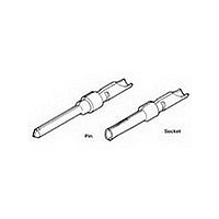
D SUB CONTACT, PIN, 18AWG, SOLDER
Manufacturer
TE Connectivity
Type
Contactr
Series
AMPLIMITE HDP-20r
Specifications of 66570-8
Number Of Contacts
1POS
Number Of Terminals
1
Plug / Receptacle
PIN
Contact Plating
Au over Pd Ni
Contact Pitch (mm)
Not Requiredmm
Body Orientation
Straight
Mounting Style
Cable
Number Of Ports
1Port
Number Of Contact Rows
Not Required
Operating Temp Range
-55C to 105C
Termination Method
Solder Cup
Housing Material
Not Required
Contact Material
Brass
Product Length (mm)
14.98mm
Product Depth (mm)
2.15mm
Wire Size (awg)
18
Contact Termination
Solder
Contact Type
Signal
Contact Size
20
Accessory Type
D Sub Contact
Gender
Pin
Rohs Compliant
Yes
Contact Gender
Pin
Product Type
Contact
Product Series
HDP-20 (Crimp Snap)
Termination Method To Wire/cable
Solder
Insulation Support
No
Grade
Standard
Contact Retention In Housing
Crimp Snap-In
Solder Tail Contact Plating
Gold Flash over Nickel
Pin Diameter (mm [in])
1.02 [0.040]
Wire Range (mm² [awg])
0.8 - 0.9 [18]
Used With
CPC Connectors, AMPLIMITE HDP-20
Contact Base Material
Brass
Contact Plating, Mating Area, Material
Gold Flash over Palladium Nickel or Gold (30) over Nickel
Contact Configuration
Solder Cup
Rohs/elv Compliance
RoHS compliant, ELV compliant
Lead Free Solder Processes
Not relevant for lead free process
Rohs/elv Compliance History
Always was RoHS compliant
Packaging Method
Loose Piece
Packaging Quantity
100/Box
Lead Free Status / RoHS Status
Compliant


Contact retention force.
Contact engaging force.
Contact separating force.
Crim p tensile.
Therm al shock.
Hum idity/tem perature cycling.
Tem perature life.
Mixed flowing gas.
Rev F
NOTE
Test Description
Shall meet visual requirements, show no physical damage, and meet requirements of additional
tests as specified in the Product Qualification and Requalification Test Sequence shown in Figure
2.
Contacts shall nor dislodge from
housing when subjected to a
m inim um force of 44.5 N [10 lbf].
2.2 N [8 ozf] m axim um per contact. EIA-364-37.
0.208 N [.75 ozf] m inim um per
contact.
See Note.
See Note.
See Note.
See Note.
W ire Size
(AW G)
18
20
22
24
26
28
ENVIRONMENTAL
Figure 1 (end)
Requirem ent
(N [lbf] m inim um )
Crim p Tensile
120.1 [27]
89 [20]
53.4 [12]
35.6 [8]
20 [4.5]
12 [2.7]
EIA-364-29.
Apply specified to contacts in an
axial direction and hold for 6
seconds.
Measure force necessary to insert
gage A to a depth of 5.6 m m [.220
in].
See Figure 6.
EIA-364-37.
Size 2 tim es using gage A. Insert
gage B to a depth of 5.6 m m [.220
in] and m easure force necessary to
separate gage B.
See Figure 6.
EIA-364-8.
Determ ine crim p tensile at a
m axim um rate of 25.4 m m [1 in] per
m inute.
EIA-364-32, Test Condition VII.
Subject unm ated specim ens to 5
cycles between -55 and 105°C.
EIA-364-31, Method III with cold
shock.
Subject m ated specim ens to 10
cycles (10 days) between 25 and
65°C at 80 to 100% RH.
EIA-364-17, Method A, Test
Condition 4, Test Tim e Condition C.
Subject m ated specim ens to 105°C
for 500 hours.
EIA-364-65, Class IIIA (4 gas).
Subject m ated specim ens to
environm ental Class IIIA for 20
days.
Procedure
108-40005
4 of 10
Related parts for 66570-8
Image
Part Number
Description
Manufacturer
Datasheet
Request
R

Part Number:
Description:
D SUB CONTACT, PIN, 18AWG, SOLDER
Manufacturer:
TE Connectivity
Datasheet:

Part Number:
Description:
20 DF PIN PLTD
Manufacturer:
TE Connectivity
Datasheet:

Part Number:
Description:
SOCKET KIT, D, 9WAY
Manufacturer:
HARTING
Datasheet:
Part Number:
Description:
PLUG KIT, D, 9WAY
Manufacturer:
HARTING
Datasheet:
Part Number:
Description:
PLUG KIT, D, 25WAY
Manufacturer:
HARTING
Datasheet:

Part Number:
Description:
High Speed / Modular Connectors 30P HEADER ASSY
Manufacturer:
TE Connectivity
Datasheet:

Part Number:
Description:
High Speed / Modular Connectors REC 6X005P R/A LT B-PLANE HS3
Manufacturer:
TE Connectivity
Datasheet:

Part Number:
Description:
High Speed / Modular Connectors 2MM HM RCPT 50P R/A AU
Manufacturer:
TE Connectivity
Datasheet:

Part Number:
Description:
High Speed / Modular Connectors 2MM HM RCPT 50P R/A AU
Manufacturer:
TE Connectivity
Datasheet:


Part Number:
Description:
Manufacturer:
TE Connectivity
Datasheet:


Part Number:
Description:
Manufacturer:
TE Connectivity
Datasheet:

Part Number:
Description:
Manufacturer:
TE Connectivity
Datasheet:

Part Number:
Description:
Manufacturer:
TE Connectivity
Datasheet: