66570-8 TE Connectivity, 66570-8 Datasheet - Page 8
66570-8
Manufacturer Part Number
66570-8
Description
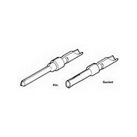
D SUB CONTACT, PIN, 18AWG, SOLDER
Manufacturer
TE Connectivity
Type
Contactr
Series
AMPLIMITE HDP-20r
Specifications of 66570-8
Number Of Contacts
1POS
Number Of Terminals
1
Plug / Receptacle
PIN
Contact Plating
Au over Pd Ni
Contact Pitch (mm)
Not Requiredmm
Body Orientation
Straight
Mounting Style
Cable
Number Of Ports
1Port
Number Of Contact Rows
Not Required
Operating Temp Range
-55C to 105C
Termination Method
Solder Cup
Housing Material
Not Required
Contact Material
Brass
Product Length (mm)
14.98mm
Product Depth (mm)
2.15mm
Wire Size (awg)
18
Contact Termination
Solder
Contact Type
Signal
Contact Size
20
Accessory Type
D Sub Contact
Gender
Pin
Rohs Compliant
Yes
Contact Gender
Pin
Product Type
Contact
Product Series
HDP-20 (Crimp Snap)
Termination Method To Wire/cable
Solder
Insulation Support
No
Grade
Standard
Contact Retention In Housing
Crimp Snap-In
Solder Tail Contact Plating
Gold Flash over Nickel
Pin Diameter (mm [in])
1.02 [0.040]
Wire Range (mm² [awg])
0.8 - 0.9 [18]
Used With
CPC Connectors, AMPLIMITE HDP-20
Contact Base Material
Brass
Contact Plating, Mating Area, Material
Gold Flash over Palladium Nickel or Gold (30) over Nickel
Contact Configuration
Solder Cup
Rohs/elv Compliance
RoHS compliant, ELV compliant
Lead Free Solder Processes
Not relevant for lead free process
Rohs/elv Compliance History
Always was RoHS compliant
Packaging Method
Loose Piece
Packaging Quantity
100/Box
Lead Free Status / RoHS Status
Compliant


Rev F
NOTE
To determine acceptable current carrying capacity per contact for percentage connector loading
and wire gage indicated, use the Multiplication Factor (F) from the above chart and multiply it times
the Base rated Current for a single circuit at the maximum ambient operating temperature shown in
Figure 4A.
Connector Loading
Single contact
Single Circuit, I
Percent
100
26
50
76
Rated Current vs Am bient Tem perature Rating For
RMS
or I , Maxim um W ire Gage, Continuous Operation
.384
.237
.164
.132
.114
28
Current Carrying Capability
DC
Current Rating
.450
.278
.193
.155
.134
26
Figure 4A
Figure 4B
W ire Size AW G
.536
.342
.229
.184
.159
24
.647
.400
.277
.222
.192
22
.795
.491
.341
.273
.236
20
.618
.428
.344
.297
18
1
108-40005
8 of 10
Related parts for 66570-8
Image
Part Number
Description
Manufacturer
Datasheet
Request
R

Part Number:
Description:
D SUB CONTACT, PIN, 18AWG, SOLDER
Manufacturer:
TE Connectivity
Datasheet:

Part Number:
Description:
20 DF PIN PLTD
Manufacturer:
TE Connectivity
Datasheet:

Part Number:
Description:
SOCKET KIT, D, 9WAY
Manufacturer:
HARTING
Datasheet:
Part Number:
Description:
PLUG KIT, D, 9WAY
Manufacturer:
HARTING
Datasheet:
Part Number:
Description:
PLUG KIT, D, 25WAY
Manufacturer:
HARTING
Datasheet:

Part Number:
Description:
High Speed / Modular Connectors 30P HEADER ASSY
Manufacturer:
TE Connectivity
Datasheet:

Part Number:
Description:
High Speed / Modular Connectors REC 6X005P R/A LT B-PLANE HS3
Manufacturer:
TE Connectivity
Datasheet:

Part Number:
Description:
High Speed / Modular Connectors 2MM HM RCPT 50P R/A AU
Manufacturer:
TE Connectivity
Datasheet:

Part Number:
Description:
High Speed / Modular Connectors 2MM HM RCPT 50P R/A AU
Manufacturer:
TE Connectivity
Datasheet:


Part Number:
Description:
Manufacturer:
TE Connectivity
Datasheet:


Part Number:
Description:
Manufacturer:
TE Connectivity
Datasheet:

Part Number:
Description:
Manufacturer:
TE Connectivity
Datasheet:

Part Number:
Description:
Manufacturer:
TE Connectivity
Datasheet: