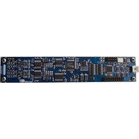
CRD-5376 Cirrus Logic Inc, CRD-5376 Datasheet - Page 21

CRD-5376
Manufacturer Part Number
CRD-5376
Description
Audio Modules & Development Tools Ref Bd LP Mlt-Ch Decimation Filter
Manufacturer
Cirrus Logic Inc
Datasheet
1.CRD-5376.pdf
(68 pages)
Specifications of CRD-5376
Description/function
Audio D/A
Operating Supply Voltage
3.3 V
Product
Audio Modules
Supply Current
300 mA
For Use With/related Products
CS3301A, CS3302A, CS4373A, CS5371A, CS5372A, CS5376A
Lead Free Status / RoHS Status
Lead free / RoHS Compliant
The secondary serial port (SPI 2) and boundary scan JTAG port are unused on CRD5376.
2.3.1.1
The CS5376A digital filter creates the analog sampling clock used by the CS5372A ∆Σ modulators and
CS4373A test DAC. MCLK has strict jitter requirements to guarantee the accuracy of analog-to-digital and
digital-to-analog conversion, and so is carefully routed between the digital filter and modulators / test
DAC.
The CS3301A amplifier also requires an analog sampling clock to run the internal chopper stabilization
circuitry, but without the strict jitter or speed requirement as needed by the CS5372A ∆Σ modulators.
Therefore, the CS3301A amplifier can run equally well from the full-speed MCLK or half-speed MCLK/2.
Although MCLK could be used as the amplifier input clock, using MCLK/2 isolates the sensitive
modulator / test DAC analog sampling clock from the amplifier clock.
2.3.1.2
Configuration of the CS5376A digital filter is through the SPI 1 port by the on-board 8051 microcontroller
which receives commands from the PC evaluation software via the USB interface. Evaluation software
commands can write/read digital filter registers, specify digital filter coefficients and test bit stream data,
and start/stop digital filter operation.
How the digital filter receives configuration information, either from a microcontroller or configuration EE-
PROM, is selected by the BOOT signal. The BOOT signal is tied low on CRD5376 for microcontroller
configuration.
2.3.1.3
The reset, synchronization and timebreak signals to the CS5376A digital filter are generated by the on-
board microcontroller and applied to the CS5376A digital filter RESET, SYNC, and TIMEB inputs.
Data collection transactions are initiated by a rising edge on the SDTKI input, as described in the
CS5376A data sheet. Two options for providing the required SDTKI rising edge are available on
DS612RD2
SPI2 Signals
SCK2
SO
SI[1..4]
JTAG Signals
TRSTz
TMS
TCK
TDI
TDO
MCLK vs. MCLK/2 Usage
Configuration - SPI 1 Port
Digital Control Signals
Description
Serial clock output (unused on CRD5376)
Serial data output (unused on CRD5376)
Serial data inputs (unused on CRD5376)
Description
JTAG reset (unused on CRD5376)
JTAG test mode select (unused on CRD5376)
JTAG test clock input (unused on CRD5376)
JTAG test data input (unused on CRD5376)
JTAG test data output (unused on CRD5376)
CRD5376
21


