TWR-SER2 Freescale Semiconductor, TWR-SER2 Datasheet - Page 4
TWR-SER2
Manufacturer Part Number
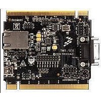
TWR-SER2
Description
MCU, MPU & DSP Development Tools SERIAL2 TOWER MODULE
Manufacturer
Freescale Semiconductor
Specifications of TWR-SER2
Processor To Be Evaluated
MCF5441X
Data Bus Width
8 bit, 16 bit, 32 bit
Interface Type
CAN, RS-232, USB
Lead Free Status / RoHS Status
Lead free / RoHS Compliant


How to build your Tower
Each elevator module is identifiable
by its four card edge connectors
Each elevator module is either Primary
or Secondary. They are identifiable
as follows:
• Primary Elevator:
• Secondary Elevator:
Gather any additional modules that
will be used to assemble your desired
Tower System configuration
TOWER SYSTEM
STEP
STEP
STEP
Written on inside top and denoted
by white card edge connectors
Written on inside bottom
3
1
2
Locate Additional
Modules
Locate the
Elevator Modules
Identify the
Elevator Modules
For each module, the words Primary and
Secondary are written along the card
edges. The Primary edge is denoted by
a white stripe
Match the white stripe on the edge of
each module to any available connector
on the Primary Elevator and plug it in
With all desired modules connected to
the Primary Elevator, carefully attach the
Secondary Elevator onto the secondary
card edges of each module
STEP
STEP
STEP
4
6
5
Identify the Primary and
Secondary Card Edges
Attach Secondary
Elevator
Plug in Primary
Card Edge
Related parts for TWR-SER2
Image
Part Number
Description
Manufacturer
Datasheet
Request
R

Part Number:
Description:
TOWER SYSTEM BOARD MPC5125
Manufacturer:
Freescale Semiconductor
Datasheet:

Part Number:
Description:
TOWER SYSTEM KIT MPC5125
Manufacturer:
Freescale Semiconductor
Datasheet:

Part Number:
Description:
TOWER SYSTEM BOARD K40X256
Manufacturer:
Freescale Semiconductor
Datasheet:

Part Number:
Description:
TOWER SYSTEM KIT MC56F8257
Manufacturer:
Freescale Semiconductor
Datasheet:

Part Number:
Description:
TOWER SYSTEM KIT K40X256
Manufacturer:
Freescale Semiconductor
Datasheet:

Part Number:
Description:
MCU, MPU & DSP Development Tools IAR KickStart Kit for Kinetis K60
Manufacturer:
Freescale Semiconductor
Datasheet:

Part Number:
Description:
TOWER SYSTEM S08LL64
Manufacturer:
Freescale Semiconductor
Datasheet:

Part Number:
Description:
KIT TOWER SYSTEM S08LH64
Manufacturer:
Freescale Semiconductor
Datasheet:

Part Number:
Description:
MCU, MPU & DSP Development Tools TOWER CD MCF51AG128 KIT
Manufacturer:
Freescale Semiconductor
Part Number:
Description:
TOWER SYSTEM S08LL64
Manufacturer:
Freescale Semiconductor
Datasheet:

Part Number:
Description:
KIT TOWER BOARD/SERIAL/ELEVATOR
Manufacturer:
Freescale Semiconductor
Datasheet:

Part Number:
Description:
KIT TOWER BOARD MCF5225X
Manufacturer:
Freescale Semiconductor
Datasheet:

Part Number:
Description:
TOWER SYSTEM S08LH64
Manufacturer:
Freescale Semiconductor
Datasheet:

Part Number:
Description:
KIT TOWER BRD/SER/ELEV MCF5225X
Manufacturer:
Freescale Semiconductor
Datasheet:

Part Number:
Description:
KIT TOWER BOARD
Manufacturer:
Freescale Semiconductor
Datasheet: