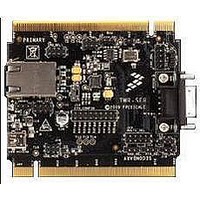
TWR-SER2 Freescale Semiconductor, TWR-SER2 Datasheet - Page 6

TWR-SER2
Manufacturer Part Number
TWR-SER2
Description
MCU, MPU & DSP Development Tools SERIAL2 TOWER MODULE
Manufacturer
Freescale Semiconductor
Specifications of TWR-SER2
Processor To Be Evaluated
MCF5441X
Data Bus Width
8 bit, 16 bit, 32 bit
Interface Type
CAN, RS-232, USB
Lead Free Status / RoHS Status
Lead free / RoHS Compliant
Configuration instructions
In this Quick Start Guide, you will learn
how to configure the various settings
on the TWR-SER2 module for use in
the Tower System.
Ethernet Settings
Refer to these settings for typical
Ethernet setting. For specific setting
details refer to the TWR-SER2 Jumper
Options section.
• 10/100 Dual RMII
• 10/100 Signal-Port RMII
• 10/100 Signal-Port MII
TOWER SYSTEM
J8 and J9 should be un-shunted
Configure SW1 (1-8) as 11000000
Configure SW2 (1-8) as 10100000
J9 should be un-shunted
Configure SW1 (1-8) as 11000000
Configure SW2 (1-8) as 10100000
J9 should be un-shunted
Configure SW1 (1-8) as 00110000
Configure SW2 (1-8) as 00010000
High Speed Dual Role
USB Settings
Refer to these settings to configure the
High-Speed USB ULPI Transceiver.
• Host Mode—TWR-SER2 will be
• Device Mode—TWR-SER2 will be
Host-Only USB Settings
Refer to these settings to configure the
Host-only USB. The TWR-SER2 will
be connected to a device, such as a
USB memory stick connected to the
standard USB Type-A receptacle.
• J16 and J21 should be shunted if
connected to a device, such as
a USB memory stick using the
appropriate mini USB adaptor.
connected to a host, such as a host PC.
VBUS enable/over-current control
is required
J24 should be un-shunted
J24 should be shunted, if it is
desired that the entire Tower system
be powered via this connection


