AVR-PX128A1 Olimex Ltd., AVR-PX128A1 Datasheet
AVR-PX128A1
Specifications of AVR-PX128A1


Related parts for AVR-PX128A1


AVR-PX128A1 Summary of contents
Page 1
... AVR- PX128A1 development board All boards produced by Olimex are ROHS compliant Copyright(c) 2009, OLIMEX Ltd, All rights reserved Users Manual Rev.B, May 2009 Page 1 ...
Page 2
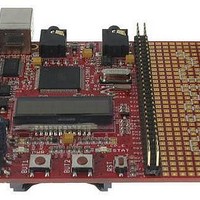
... AVR-PX128A1 board is entry level development board for the new AVR XMEGA A Microcontroller family of devices produced by Atmel Corporation. With AVR-PX128A1 you can explore the features of XMEGA A family on budged, the board have everything necessary to build simple applications: USB port where power is taken and power supply circuit, reset and oscillator circuits, JTAG and PDI port for programming and debugging, LCD, status LED and two user buttons ...
Page 3
... ELECTROSTATIC WARNING The AVR-PX128A1 board is shipped in protective anti-static packaging. The board must not be subject to high electrostatic potentials. General practice for working with static sensitive devices should be applied when working with this board. BOARD USE REQUIREMENTS Cables: The cable you will need depends on the programmer/debugger you use, also you will need USB A-B cable ...
Page 4
Real Time Counter with separate Oscillator – Two Eight-channel, 12-bit, 2 Msps Analog to Digital Converters – Two Two-channel, 12-bit, 1 Msps Digital to Analog Converters – Four Analog Comparators with Window compare function – External Interrupts on all ...
Page 5
BLOCK DIAGRAM Page 5 ...
Page 6
MEMORY MAP Page 6 ...
Page 7
SCHEMATIC + C16 100nF 100nF C15 100nF C14 100nF C13 100nF C12 100nF C11 100nF C10 100nF C9 + FT232RL C21 100nF C22 10uF/6.3V + C23 NA C24 NA USB + 7 4 C37 TEST 21 GND3 ...
Page 8
BOARD LAYOUT Page 8 ...
Page 9
... AVR-PX128A1 is typically power supplied with 9 V DC, and 6 V AC. The board power consumption is about 30mA. RESET CIRCUIT AVR-PX128A1 reset circuit includes pin 5 of PDI connector, pin 6 of JTAG connector, ATXMEGA128A1 pin 90 and Reset button. CLOCK CIRCUIT Quartz crystal 8MHz is connected to ATXMEGA128A1 pin 91 (PR0/XTAL2) and pin 92 (PR1/XTAL1) ...
Page 10
JUMPER DESCRIPTION 3.3V_E Enable the main 3.3 V regulator VR1(3.3V) – LM1117. Default state is closed. WP_E Enable SD/MMC Write Protect signal check. Default state is closed. CP_E Enable SD/MMC Card Present signal check. Default state is closed. INPUT/OUTPUT Status ...
Page 11
PDI Pin # UEXT Pin # USB Pin # Signal Name PDI_DATA 3. RST GND Signal Name 3.3V ...
Page 12
EXT Pin # 1 VCC 3 PA7 5 PA6 7 PA5 9 PA4 11 PA3 13 PA2 15 PA1 17 PA0 19 PB3 (STAT) 21 PC7 (SD_SCK) 23 PC6 (SD_MISO) 25 PC3 (E) 27 PC2 (RW) 29 PC0 31 PD7 ...
Page 13
Pin # Signal Name 1 Power Input 2 MICROPHONE Pin # Signal Name 1 AGND MIC HEADPHONE Pin # Signal Name 1 AGND 2 IN1=IN2 3 IN2=IN1 GND Page 13 ...
Page 14
SD/MMC Pin # Signal Name Pin # SD_NSS 2 GND 4 SD_SCK 6 SD_MISO 8 Via 100k to 3. Via 10k to 3.3V Page 14 Signal Name ...
Page 15
MECHANICAL DIMENSIONS All measures are in inches. Page 15 ...
Page 16
... AVAILABLE DEMO SOFTWARE AVR-PX128A1 – AVR-PX128A1 – AVR-PX128A1 – AVR-PX128A1 – AVR-PX128A1 – ADC interrupt and ADC polled UART interrupt and UART polled DAC example C source and HEX GPIO ports example C source and HEX PLL at 32Mhz with 8Mhz clock Page 16 examples C source and HEX ...
Page 17
... ORDER CODE AVR-PX128A1 How to order? You can order to us directly or by any of our distributors. Check our web Revision history: REV.B – assembled and tested www.olimex.com/dev for more info. - create May 2009 Page 17 ...
Page 18
... This document is intended only to assist the reader in the use of the product. OLIMEX Ltd. shall not be liable for any loss or damage arising from the use of any information in this document or any error or omission in such information or any incorrect use of the product ...