AVR-PX128A1 Olimex Ltd., AVR-PX128A1 Datasheet - Page 10
AVR-PX128A1
Manufacturer Part Number
AVR-PX128A1
Description
MCU, MPU & DSP Development Tools DEV PROTOTYPE BRD FOR ATMEGA128A1
Manufacturer
Olimex Ltd.
Datasheet
1.AVR-PX128A1.pdf
(18 pages)
Specifications of AVR-PX128A1
Processor To Be Evaluated
ATXMEGA128A1
Data Bus Width
8 bit, 16 bit
Interface Type
USB, JTAG
Dimensions
3.9 in x 3.15 in
Operating Supply Voltage
1.6 V to 3.6 V
Lead Free Status / RoHS Status
Lead free / RoHS Compliant


JUMPER DESCRIPTION
3.3V_E
WP_E
CP_E
INPUT/OUTPUT
CONNECTOR DESCRIPTIONS
JTAG
Enable the main 3.3 V regulator VR1(3.3V) – LM1117.
Default state is closed.
Enable SD/MMC Write Protect signal check.
Default state is closed.
Enable SD/MMC Card Present signal check.
Default state is closed.
1
2
3
4
5
6
7
8
9
10
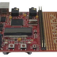
Status LED (green) with name STAT connected to ATXMEGA128A1 pin 8
(PB3/ADC3B/AC3B/DAC1B) and EXT pin PB3.
Power-on LED (red) with name PWR – this led shows that +3.3V is applied to the
board.
User button with name BUT1 connected to ATXMEGA128A1 pin 35
(PE0/OC0AE/#OC0AE/SDAE).
User button with name BUT2 connected to ATXMEGA128A1 pin 36
(PE1/OC0BE/#XCK0E/SCLE).
Reset button with name RST connected to pin 5 of PDI connector, pin 6 of JTAG
connector, ATXMEGA128A1 pin 90 (#RESET/PDI_CLOCK).
Pin #
PB6
GND
PB7
3.3V
PB4
RST
3.3V
NC
PB5
GND
Signal Name
Page 10
Related parts for AVR-PX128A1
Image
Part Number
Description
Manufacturer
Datasheet
Request
R

Part Number:
Description:
VARISTOR 8V 3A 100PF 0402 SMD
Manufacturer:
TDK Corporation
Datasheet:
Part Number:
Description:
VARISTOR 12V 10A 130PF 0402 SMD
Manufacturer:
TDK Corporation
Datasheet:
Part Number:
Description:
VARISTOR 27V 4A 40PF 0402 SMD
Manufacturer:
TDK Corporation
Datasheet:
Part Number:
Description:
VARISTOR 8V 25A 650PF 0402 SMD
Manufacturer:
TDK Corporation
Datasheet:

Part Number:
Description:
VARISTOR 27V 2A 30PF 0603 SMD
Manufacturer:
TDK Corporation
Datasheet:
Part Number:
Description:
VARISTOR 18V 30A 600PF 0603 SMD
Manufacturer:
TDK Corporation
Datasheet:
Part Number:
Description:
VARISTOR 8V 30A 650PF 0603 SMD
Manufacturer:
TDK Corporation
Datasheet:
Part Number:
Description:
VARISTOR 27V 20A 160PF 0603 SMD
Manufacturer:
TDK Corporation
Datasheet:
Part Number:
Description:
VARISTOR 27V 48A 430PF 0603 SMD
Manufacturer:
TDK Corporation
Datasheet:
Part Number:
Description:
VARISTOR 12V 50A 1050PF 0603 SMD
Manufacturer:
TDK Corporation
Datasheet:
Part Number:
Description:
VARISTOR 22V 30A 560PF 0603 SMD
Manufacturer:
TDK Corporation
Datasheet:
Part Number:
Description:
VARISTOR 22V 10A 210PF 0603 SMD
Manufacturer:
TDK Corporation
Datasheet:

Part Number:
Description:
VARISTOR 39V 100A 430PF 0805 SMD
Manufacturer:
TDK Corporation
Datasheet:
Part Number:
Description:
VARISTOR 12V 60A 1000PF 0805 SMD
Manufacturer:
TDK Corporation
Datasheet:
Part Number:
Description:
VARISTOR 22V 100A 800PF 0805 SMD
Manufacturer:
TDK Corporation
Datasheet: