VUB120-12NO2 IXYS, VUB120-12NO2 Datasheet
VUB120-12NO2
Manufacturer Part Number
VUB120-12NO2
Description
RECT BRIDGE 3PH 1200V V2-PACK
Manufacturer
IXYS
Specifications of VUB120-12NO2
Voltage - Peak Reverse (max)
1200V
Current - Dc Forward (if)
188A
Diode Type
Three Phase - IGBT with Diode
Speed
Standard Recovery >500ns, > 200mA (Io)
Mounting Type
PCB
Package / Case
V2-PAK
Channel Type
N
Configuration
Single
Collector-emitter Voltage
1.2kV
Gate To Emitter Voltage (max)
±20V
Mounting
Screw
Operating Temperature (min)
-40C
Operating Temperature (max)
150C
Operating Temperature Classification
Automotive
Vrrm, Rect, (v)
1200
Idav, Rec, (a)
188
@ Th, Rect, (°c)
-
@ Tc, Rect, (°c)
80
Vces, Igbt, (v)
1200
Ic80, Igbt, (a)
100
Vrrm, Fast Diode, (v)
1200
If(av), Fast Diode, (a)
34
Trr, Fast Diode, (ns)
40
Package Style
V2-Pack
Lead Free Status / RoHS Status
Lead free / RoHS Compliant
Reverse Recovery Time (trr)
-
Lead Free Status / RoHS Status
Compliant, Lead free / RoHS Compliant


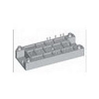
Three Phase Rectifier Bridge
with IGBT and Fast Recovery Diode
for Braking System
Preliminary Data
V
1200 VUB 120-12 NO2(T)
1200 VUB 160-12 NO2(T)
(T) = NTC optional
Symbol
V
I
I
I
P
V
V
I
I
I
P
V
I
I
I
P
T
T
T
V
M
d
d
a
Weight
Data according to IEC 60747
IXYS reserves the right to change limits, test conditions and dimensions.
© 2006 IXYS All rights reserved
dAVM
FSM
2
C25
C80
CM
FAV
FRMS
FSM
V
t
VJ
VJM
stg
S
A
RRM
RRM
tot
CES
GE
tot
RRM
tot
ISOL
d
Type
Conditions
T
T
T
T
T
T
T
Continuous
T
T
T
t
T
T
T
T
T
T
50/60 Hz
I
Mounting torque
Creep distance on surface
Strike distance in air
Maximum allowable acceleration
typ.
p
ISOL
C
VJ
VJ
VJ
VJ
C
VJ
C
C
C
C
C
C
VJ
VJ
C
≤ 1 mA
= 80°C, rect., d =
= 45°C,
= 150°C,
= 45°C,
= 150°C,
= 25°C per diode
= 25°C to 150°C
= 25°C, DC
= 80°C, DC
= 80°C, d = 0.5
= Pulse width limited by T
= 25°C
= 80°C, rect. d = ½
= 80°C, rect. d = ½
= 45°C,
= 150°C,
= 25°C
V
1600 VUB 120-16 NO2(T)
1600 VUB 160-16 NO2(T)
RRM
V
Type
1
t = 10 ms, V
t = 10 ms, V
t = 10 ms, V
t = 10 ms, V
t = 10 ms
t = 10 ms
t = 1 min
t = 1 s
(M5)
(10-32 UNF)
/
3
VJM
R
R
R
R
= 0 V
= 0 V
= 0 V
= 0 V
A6~
E6~
K6~
VUB 120
1200
± 20
140
100
280
570
Maximum Ratings
95
M1/O1
M/O
10
-40...+150
-40...+125
1200/1600
W U S/T
VUB160
10
18-22 lb.in.
2-2.5 Nm
1100
6050
4610
1200
1200
3000
3600
S 1
± 20
12.7 mm
188
960
160
177
125
350
690
200
180
140
150
9.4 mm
95
34
48
50 m/s
80
U1/
W1
W 5
W 6
V~
V~
°C
°C
°C
W
W
W
V
A
A
A
A
A
V
V
A
A
A
A
V
A
A
A
A
g
2
V
I
Features
• Soldering connections for PCB mounting
• Isolation voltage 3600 V~
• Ultrafast diode
• Convenient package outline
• UL registered E 72873
• Case and potting UL94 V-0
• optional NTC
Applications
• Drive Inverters with brake system
Advantages
• 2 functions in one package
• Easy to mount with two screws
• Suitable for wave soldering
• High temperature and power cycling
dAVM
capability
RRM
= 1200/1600 V
= 188 A
VUB 120 / 160
1 - 3
Related parts for VUB120-12NO2
Image
Part Number
Description
Manufacturer
Datasheet
Request
R

Part Number:
Description:
3-Phase Rectifier Bridge with Brake
Manufacturer:
IXYS
Datasheet:
Part Number:
Description:
3-Phase Rectifier Bridge with Brake
Manufacturer:
IXYS
Datasheet:

Part Number:
Description:
RECT BRIDGE 3PH 1600V V2-PACK
Manufacturer:
IXYS
Datasheet:

Part Number:
Description:
Three Phase Rectifier Bridge with IGBT and Fast Recovery Diode for Braking System
Manufacturer:
IXYS [IXYS Corporation]
Datasheet:

Part Number:
Description:
Three Phase Rectifier Bridge With Igbt And Fast Recovery Diode For Braking System
Manufacturer:
IXYS Corporation
Datasheet:
Part Number:
Description:
HiPerFET Power MOSFETs
Manufacturer:
IXYS Corporation
Datasheet:
Part Number:
Description:
J-K-Type Flip-Flop
Manufacturer:
IXYS Corporation
Datasheet:
Part Number:
Description:
HiPerRF Power MOSFETs
Manufacturer:
IXYS Corporation
Datasheet:
Part Number:
Description:
Rectifier Module for Three Phase Power Factor Correction
Manufacturer:
IXYS Corporation
Datasheet:
Part Number:
Description:
Thyristor Modules Thyristor/Diode Modules
Manufacturer:
IXYS Corporation
Datasheet:
Part Number:
Description:
Thyristor Modules Thyristor/Diode Modules
Manufacturer:
IXYS Corporation
Datasheet:
VUB120-12NO2 Summary of contents
Page 1
... Mounting torque d d Creep distance on surface S d Strike distance in air A a Maximum allowable acceleration Weight typ. Data according to IEC 60747 IXYS reserves the right to change limits, test conditions and dimensions. © 2006 IXYS All rights reserved M1/O1 A6~ E6~ K6 Maximum Ratings 1200/1600 1 ...
Page 2
... A/µ thJC R thCH 25° 25/50 IXYS reserves the right to change limits, test conditions and dimensions. © 2006 IXYS All rights reserved Characteristic Values (T = 25°C, unless otherwise specified) VJ min. typ. max. 1.46 0.87 0.2 1200 4.5 VUB 120 VUB 160 = 125° ...
Page 3
... Dimensions 0.0394") IXYS reserves the right to change limits, test conditions and dimensions. © 2006 IXYS All rights reserved VUB 120 / 160 Label ...