HFBR-0536Z Avago Technologies US Inc., HFBR-0536Z Datasheet - Page 4
HFBR-0536Z
Manufacturer Part Number
HFBR-0536Z
Description
KIT EVAL FIBER OPTICS 32MBD
Manufacturer
Avago Technologies US Inc.
Specifications of HFBR-0536Z
Main Purpose
Interface, Fiber Optics
Embedded
No
Utilized Ic / Part
HFBR-1527Z, HFBR-2526Z
Primary Attributes
650nm, 32MBd, TTL
Operating Voltage
5 V
Description/function
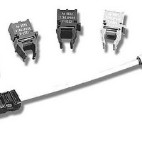
Versatile Fiber Optic Evaluation Kit
Maximum Operating Temperature
+ 85 C
Minimum Operating Temperature
- 40 C
Operating Current
6.2 mA
Silicon Manufacturer
Avago
Kit Application Type
Communication & Networking
Peak Reflow Compatible (260 C)
Yes
Leaded Process Compatible
Yes
Rohs Compliant
Yes
For Use With/related Products
HFBR-1527Z, HFBR-2526Z
Lead Free Status / RoHS Status
Lead free / RoHS Compliant
Secondary Attributes
-
Lead Free Status / Rohs Status
Details
Other names
516-2321


The 1 MHz idle signal described in the IEEE 802.3
10Base-FL standard assures that the burst-mode proto-
col used for copper wire Ethernet is converted to a pro-
tocol that will optimize the performance of a fiberoptic
receiver. More details about inexpensive fiberoptic
solutions suitable for use with higher-efficiency block
substitution codes, such as 4B5B, and 8B10B, can be
found in Avago Technologies Application Notes 1122
and 1123. This publication will stay focused on solutions
compatible with unencoded data, because many system
designers need a fiberoptic solution that can use proto-
cols originally developed for use with copper wires.
Table 1
4
Transmitter
Component Part #
and Wavelength
HFBR-15X7Z
650 nm LED
HFBR-15X7Z
650 nm LED
HFBR-15X7Z
650 nm LED
HFBR-15X7Z
650 nm LED
HFBR-14X2Z
820 nm LED
HFBR-14X2Z
820 nm LED
HFBR-14X4Z
820 nm LED
HFBR-14X4Z
820 nm LED
HFBR-13X2TZ
1300 nm LED
HFBR-13X2TZ
1300 nm LED
Receiver
Component Part #
and Wavelength
HFBR-25X6Z
650 nm
HFBR-25X6Z
650 nm
HFBR-25X6Z
650 nm
HFBR-25X6Z
650 nm
HFBR-24X6Z
820 nm
HFBR-24X6Z
820 nm
HFBR-24X6Z
820 nm
HFBR-24X6Z
820 nm
HFBR-23X6TZ
1300 nm
HFBR-23X6TZ
1300 nm
Fiber Diameter
Type
1 mm plastic
step index
1 mm plastic
step index
200 mm
HCS step index
200 mm
HCS step index
200 mm
HCS step index
200 mm
HCS step index
62.5/125 mm
multimode glass
62.5/125 mm
multimode glass
62.5/125 mm
multimode glass
62.5/125 mm
multimode glass
Distances and Data Rates Achievable
The simple transceivers recommended in this applica-
tion note can be used to address a very wide range
of distances, data rates, and system cost targets. The
maximum distances allowed with various types of
optical fiber when using Avago Technologies’ wide
range of fiberoptic transceiver components are shown
Table 1. One simple calculation is needed to optimize
the receiver for use at the desired maximum symbol rate
of your system application. No transmitter or receiver
adjustments are needed when using fiber cable length
that vary from virtually zero length up to the maximum
distances specified in Table 1.
Maximum Distance at 32 MBd
with the transceiver circuits
recommended in this publication
27 meters with transmitter in Fig. 3
and receiver in Fig. 4
42 meters with transmitter in Fig. 3
and receiver in Fig. 5
690 meters with transmitter in Fig. 3
and receiver in Fig. 4
1.0 kilometer with transmitter
in Fig. 3 and receiver in Fig. 5
690 meters with transmitter in Fig. 3
and receiver in Fig. 4
1.0 kilometer with transmitter
in Fig. 3 and receiver in Fig. 5
800 meters with transmitter in Fig. 3
and receiver in Fig. 4
1.6 kilometers with transmitter
in Fig. 3 and receiver in Fig. 5
1.3 kilometers with transmitter
in Fig 3. and receiver in Fig. 4
3.3 kilometers with transmitter
in Fig. 3 and receiver in Fig. 5
Related parts for HFBR-0536Z
Image
Part Number
Description
Manufacturer
Datasheet
Request
R

Part Number:
Description:
Fiber Optic Transmitters, Receivers, Transceivers 1300nm 155MBd 16-pin DIP ST Rx
Manufacturer:
Avago Technologies US Inc.

Part Number:
Description:
FIBER OPTIC TX 125 MBD 650N
Manufacturer:
Avago Technologies US Inc.
Datasheet:

Part Number:
Description:
Fiber Optic Evaluation Kit
Manufacturer:
Avago Technologies US Inc.
Datasheet:

Part Number:
Description:
RECEIVER FIBER OPTIC ST 266MBD
Manufacturer:
Avago Technologies US Inc.
Datasheet:

Part Number:
Description:
RCVR OPT HI SPEED VERS LINK HORZ
Manufacturer:
Avago Technologies US Inc.
Datasheet:

Part Number:
Description:
RCVR OPT HI SPEED VERS LINK VERT
Manufacturer:
Avago Technologies US Inc.
Datasheet:

Part Number:
Description:
TXRX OPTICAL 850NM VCSEL MT-RJ
Manufacturer:
Avago Technologies US Inc.
Datasheet:

Part Number:
Description:
TXRX MM SFP LC CONN BAIL DELATCH
Manufacturer:
Avago Technologies US Inc.
Datasheet:

Part Number:
Description:
TXRX MMF SFP GBE/FC BAIL DELATCH
Manufacturer:
Avago Technologies US Inc.
Datasheet:

Part Number:
Description:
XMITTER FIBER OPTIC 266MBD ST
Manufacturer:
Avago Technologies US Inc.
Datasheet:

Part Number:
Description:
OPTOCOUPLER GATE DRV 2A 16-SOIC
Manufacturer:
Avago Technologies US Inc.
Datasheet:
Part Number:
Description:
OPTOCOUPLER 2CH 2.5A 16-SOIC
Manufacturer:
Avago Technologies US Inc.
Datasheet:

Part Number:
Description:
OPTOCOUPLER GATE DRV 0.4A 16SOIC
Manufacturer:
Avago Technologies US Inc.
Datasheet:

Part Number:
Description:
OPTOCOUPLER 2.0A 250KHZ 8-DIP
Manufacturer:
Avago Technologies US Inc.
Datasheet:

Part Number:
Description:
OPTOCOUPLER 2.0A 250KHZ GW 8-SMD
Manufacturer:
Avago Technologies US Inc.
Datasheet: