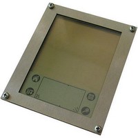
AVR-TLCD-128CAN Olimex Ltd., AVR-TLCD-128CAN Datasheet - Page 14

AVR-TLCD-128CAN
Manufacturer Part Number
AVR-TLCD-128CAN
Description
MCU, MPU & DSP Development Tools
Manufacturer
Olimex Ltd.
Datasheet
1.AVR-TLCD-128CAN.pdf
(19 pages)
Specifications of AVR-TLCD-128CAN
Processor To Be Evaluated
AT90CAN128
Data Bus Width
8 bit
Interface Type
CAN, JTAG
Dimensions
102 mm x 85 mm
Operating Supply Voltage
2.7 V to 5.5 V
Lead Free Status / RoHS Status
Lead free / RoHS Compliant
UEXT:
TXD
RXD
SCL
the data transfer through I2C interface. This could be either input or output depending on
whether the MCU is master or slave.
SDA
flow direction) for the I2C interface.
MISO
master) or data output(MCU is slave). The signal is pat of the SPI interface.
MOSI
SPI interface and it is either data output from the MCU (when it is master) or data input for
the MCU (when it is slave).
SCK
for the data transfer through the SPI interface. It could be either input or output depending
on whether the MCU is master or slave.
PWR:
Input
I/O
I/O
1
2
3
4
5
6
7
8
9
10
1
2
I/O
Output Transmit Data. This is the output data line for the UART.
I/O
I/O
At the PWR pin should be applied voltage 4.5VAC or +(6-9)VDC.
Pin #
Pin #
Receive Data. This is the input data line for the UART.
Serial (Synchronization) Clock. This is the synchronization clock for
Serial Data. This pin is data input or output (depending on the data
Master In Slave Out. This pin could be either data input (MCU is
Master Out Slave In. This pin is be used for communication through
Serial (Synchronization) Clock . This is the synchronization clock
+3.3V
GND
TXD
RXD
SCL
SDA
MISO
MOSI
SCK
SS
PWR
GND
Signal Name
Signal Name


