ATA6621-EK Atmel, ATA6621-EK Datasheet - Page 3
ATA6621-EK
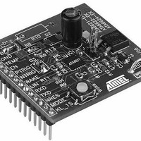
Manufacturer Part Number
ATA6621-EK
Description
MCU, MPU & DSP Development Tools Demoboard LIN SBC
Manufacturer
Atmel
Datasheet
1.ATA6622-EK.pdf
(19 pages)


4970B–AUTO–03/11
Table 1-3.
Table 1-4.
As the window watchdog of the Atmel
mode (Fail-safe mode), a periodic reset signal will be generated at the pin NRES as long as no
trigger signal can be received at the watchdog trigger input. Normally the connected microcon-
troller will be monitored by the watchdog, so it has to generate the required trigger signal as
described in
device. For the quick start it is sufficient to generate a square-wave signal with V
f = 75Hz at pin NTRIG or PTRIG for the Atmel ATA6621 or with f = 50Hz at pin NTRIG for the
Atmel ATA6622/24/26 (this is recommended only for testing purposes). In order to check that
the watchdog is triggered in the expected way, the reset pin NRES can be monitored until a
continuous high level is available.
Please note that the communication is still inactive in Pre-normal mode (Fail-safe mode).
In order to communicate via the LIN bus interface you have to switch to normal mode by
applying the VCC voltage (5V or 3.3V, as appropriate) at pin EN.
Fail-safe mode
Fail-safe mode
Normal mode
Normal mode
Mode
Mode
Section 2.3 on page 4
Atmel ATA6622
Atmel ATA6624/26
VCC
3.3V
3.3V
VCC
5V
5V
WD_OSC
WD_OSC
1.23V
1.23V
1.23V
1.23V
and in more detail in the datasheet of the corresponding
®
ATA6621/22/24/26 is already active in the Pre-normal
TEMP
TEMP
-
-
-
-
Atmel ATA6621/22/24/26
INH
INH
On
On
On
On
RXD
3.3V
3.3V
RXD
5V
5V
TXD dependent
TXD dependent
Recessive
Recessive
LIN
LIN
PP
Transceiver
Transceiver
= VCC and
Off
On
Off
On
3
Related parts for ATA6621-EK
Image
Part Number
Description
Manufacturer
Datasheet
Request
R

Part Number:
Description:
IC TXRX LIN BUS 5V/50MA 20QFN
Manufacturer:
Atmel
Datasheet:

Part Number:
Description:
DEV KIT FOR AVR/AVR32
Manufacturer:
Atmel
Datasheet:

Part Number:
Description:
INTERVAL AND WIPE/WASH WIPER CONTROL IC WITH DELAY
Manufacturer:
ATMEL Corporation
Datasheet:
Part Number:
Description:
Low-Voltage Voice-Switched IC for Hands-Free Operation
Manufacturer:
ATMEL Corporation
Datasheet:
Part Number:
Description:
MONOLITHIC INTEGRATED FEATUREPHONE CIRCUIT
Manufacturer:
ATMEL Corporation
Datasheet:
Part Number:
Description:
AM-FM Receiver IC U4255BM-M
Manufacturer:
ATMEL Corporation
Datasheet:
Part Number:
Description:
Monolithic Integrated Feature Phone Circuit
Manufacturer:
ATMEL Corporation
Datasheet:
Part Number:
Description:
Multistandard Video-IF and Quasi Parallel Sound Processing
Manufacturer:
ATMEL Corporation
Datasheet:
Part Number:
Description:
High-performance EE PLD
Manufacturer:
ATMEL Corporation
Datasheet:
Part Number:
Description:
8-bit Flash Microcontroller
Manufacturer:
ATMEL Corporation
Datasheet:
Part Number:
Description:
2-Wire Serial EEPROM
Manufacturer:
ATMEL Corporation
Datasheet: