REP430F Elprotronic Inc., REP430F Datasheet - Page 10
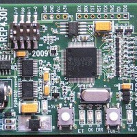
REP430F
Manufacturer Part Number
REP430F
Description
Programmers & Debuggers MSP430 MCU Replicatr
Manufacturer
Elprotronic Inc.
Datasheet
1.REP430F.pdf
(21 pages)
Specifications of REP430F
Lead Free Status / RoHS Status
Lead free / RoHS Compliant


4.1 Powering REP430F
The REP430F replicator can be powered in several ways:
*
*
*
*
*
powered from the supply that supplies the highest voltage.
blowing the physical security fuse in the target devices MSP320F1xx, F2xx or F4xx feature
is used. If the REP430F board is used with targets F5xx, F6xx (with or without blowing
the security fuse option) or with targets F1xx, F2xx, F4xx without blowing the security fuse
option, then the board can be supplied from external power supply as low as 4V. If board is
supplied with a voltage lower than 4V, then the functionality is still available, however
setting the Vcc target device can be limited to lower voltage only.
REP430F -
DC jack connector with standard DC jack power connectors with a 1.95mm center
pin and external connector diameter 6.0 mm . The center pin is used for the positive
voltage. A 4-10V DC power supply should be used. The onboard voltage regulators
supplies Vcc 3.0V to the board and Vpp 6.5V to blow the security fuse circuit.
Terminal block power supply. Ground should be connected to the GND terminal on
the power connector (see Figure 4.1). A 4-10V supply can be connected to the “9V”
terminal.
Power supply from target device connector - pin 4. Ground should be connected to
pin 9 and a 4-10V supply can be connected to pin-4 of the Target’s connector.
Power supply from target device connector - pin 2. Ground should be connected to
pin 9 and the Vcc taken directly from the target’s MCU Vcc (2.5V to 3.6V) can be
connected to pin-2 of the Target’s connector.
Power supply from the Host JTAG connector. Ground should be connected to pin 9
and the Vcc (2.5 to 3.6V) taken directly from the Host JTAG adapter connected to
pin-2 of the Target’s connector. Switch “Vcc from Host SW” should be on “ON”
position (see figure 4.1)
If several power sources are connected to REP430F replicator the board will be
The board should be supplied from external power supply 8 to 10V (min 200mA) if
User Guide
PM041A01 Rev.0
10
Related parts for REP430F
Image
Part Number
Description
Manufacturer
Datasheet
Request
R

Part Number:
Description:
Programmers & Debuggers FlashPro430 LITE FOR TI MSP430 MCU
Manufacturer:
Elprotronic Inc.

Part Number:
Description:
Programmers & Debuggers GangPro430 FOR TI MSP430 MCU
Manufacturer:
Elprotronic Inc.

Part Number:
Description:
Programmers & Debuggers GANG SPLITTER FOR GangPro430
Manufacturer:
Elprotronic Inc.

Part Number:
Description:
Programmers & Debuggers FlashPro-CC STD. FOR TI CHIPCON MCU
Manufacturer:
Elprotronic Inc.

Part Number:
Description:
Programmers & Debuggers GangPro-CC FOR TI CHIPCON MCU
Manufacturer:
Elprotronic Inc.

Part Number:
Description:
Programmers & Debuggers FlashPro2000 STD FOR TI C2000 DSP
Manufacturer:
Elprotronic Inc.

Part Number:
Description:
Programmers & Debuggers FlashPro430/ FlashPro-CC STD VER.
Manufacturer:
Elprotronic Inc.
Part Number:
Description:
Programmers & Debuggers GangPro430 JTAG/SBW
Manufacturer:
Elprotronic Inc.
Part Number:
Description:
Programmers & Debuggers FlashPro430 STD FOR TI MSP430 MCU
Manufacturer:
Elprotronic Inc.
Part Number:
Description:
Programmers & Debuggers FlashPro430 LITE JTAG/SBW
Manufacturer:
Elprotronic Inc.

Part Number:
Description:
Development Software Software Upgrade for USB-MSP430-FPA-GANGJ
Manufacturer:
Elprotronic Inc.
Part Number:
Description:
Programmers & Debuggers FlashPro2000 LITE VERSION
Manufacturer:
Elprotronic Inc.
Part Number:
Description:
Programmers & Debuggers FlashPro430 LITE BSL ONLY
Manufacturer:
Elprotronic Inc.
Part Number:
Description:
Programmers & Debuggers FlashPro-CC LITE VERSION
Manufacturer:
Elprotronic Inc.