V23993-EVA1035-H VINCOTECH, V23993-EVA1035-H Datasheet
V23993-EVA1035-H
Specifications of V23993-EVA1035-H


Related parts for V23993-EVA1035-H


V23993-EVA1035-H Summary of contents
Page 1
... GPS Evaluation Kit EVA1035-H A Description of the Evaluation Board for Vincotech’s GPS Receiver / Smart Antenna Module A1035-H User’s Manual Hardware Revision 01 Version 1.0 ...
Page 2
Revision History Rev. Date 0.1 12-30-08 1.0 01-26-09 mm-dd-yy V1.0 – Feb-09 Description Initial Draft, based on EVA1084-A and A1035-H manuals First release User’s Manual Page ...
Page 3
... THE AVAILABILITY OF SUCH EXTERNAL SITES OR RESOURCES, AND DOES NOT ENDORSE AND IS NOT RESPONSIBLE OR LIABLE FOR ANY CONTENT, ADVERTISING, PRODUCTS, OR OTHER MATERIALS ON OR AVAILABLE FROM SUCH SITES OR RESOURCES. VINCOTECH SHALL NOT BE RESPONSIBLE OR LIABLE, DIRECTLY OR INDIRECTLY, FOR ANY DAMAGE OR LOSS CAUSED OR ALLEGED TO BE CAUSED CONNECTION WITH USE OF OR RELIANCE ON ANY SUCH CONTENT, GOODS OR SERVICES AVAILABLE ON OR THROUGH ANY SUCH SITE OR RESOURCE ...
Page 4
Table of Contents 1 Introduction ........................................................................................................ 5 1.1 Purpose............................................................................................................. 5 1.2 Contents............................................................................................................ 5 2 Handling Precautions ........................................................................................ 6 3 Quick Start (using USB connection) ................................................................ 6 4 On-Board Peripherals ........................................................................................ 9 4.1 RESET and ON_OFF Push-Button ................................................................... 9 4.2 External ...
Page 5
... Introduction 1.1 Purpose The GPS Evaluation Kit EVA1035-H allows an easy evaluation of Vincotech’s GPS receiver /smart antenna module A1035-H by offering quick access to the ports of the module. The EVA1035-H serves three major purposes: • demonstration package of the module’s capabilities Powering the A1035-H GPS receiver module via the USB connector with suffi- cient view to the sky (or using an external active antenna with sufficient view to the sky) will result in an NMEA output with position information ...
Page 6
Handling Precautions The EVA1035-H contains components that are sensitive to electrostatic discharge (ESD). Please handle with appropriate care. 3 Quick Start (using USB connection) (1) Connect the EVA1035-H with your PC using the included USB cable. (2) When the ...
Page 7
Figure 2: Disabling of Microsoft Serial BallPoint (3) Either assure that the on-module GPS antenna has good view to the sky or con- nect the included GPS antenna to the EVA1035-H via the external antenna con- nector and make sure ...
Page 8
Figure 4: GPS Cockpit communication window – COM2 The connection is established now. (6) Open a terminal window to see NMEA sentences by using the “NMEA Terminal” window button. You should then see messages like this: Figure 5: GPS Cockpit ...
Page 9
On-Board Peripherals 4.1 RESET and ON_OFF Push-Button The EVA1035-H holds two push-buttons: • nRST (RESET) • ON_OFF The nRST button is used to get a full reset of the GPS module. All parameters are stored in non-volatile memory. After ...
Page 10
... Further information is given in • Chapter “6.2 DIP Switch Settings” and • Vincotech’s GPS Receiver A1035-H Product Manual 4.2.1 Hints If the external antenna input is not used it should be terminated with 50 Ω ± 20%. Do not feed antenna supply voltage into terminated antenna inputs. ...
Page 11
LED’s There are 6 LED’s on the EVA1035-H that indicate different signals from the GPS receiver (order of LED’s on EVA1035-H from left to right): LED Name LD2 RX LD1 TX LD4 ON_OFF LD5 1PPS LD3 RFPWUP LD6 Power ...
Page 12
Design-in Support The EVA1035-H demo board offers the possibility to implement the A1035-H GPS receiver module temporarily into your design by using the terminal block with 9 con- nections. To operate the EVA1035-H via this terminal block, please check ...
Page 13
DIP Switch Settings The following picture shows the DIP switches of the EVA1035-H. Switch Function S1 BOOTSEL S2 RFPWUP S3 ON_OFF S4 RX0 S5 TX0 S6 ANT_SW S7 VBAK S8 VCC *1: S7 has to be OFF to use ...
Page 14
... Standard NMEA-0183 output on NMEA, baud rate selectable. • Standard USB connectors 8 EVA1035-H Firmware and NMEA Sentences See separate document GPS Firmware for a detailed description of the standard firmware loaded onto the modules delivered with the EVA1035-H. V1.0 – Feb-09 Figure 10: ICC jumper User’s Manual ...
Page 15
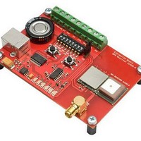
Board Overview V1.0 – Feb-09 Figure 11: Board overview User’s Manual Page ...
Page 16
Board Schematics V1.0 – Feb-09 Figure 12: EVA1035-H board schematics User’s Manual Page ...
Page 17
... This manual was created with due diligence. We hope that it will be helpful to the user to get the most out of the GPS module. Inputs regarding errors or mistaken verbalizations and comments or proposals to Vincotech, Germany, for further improvements are highly appreciated. Vincotech GmbH Biberger Str. 93 82008 Unterhaching (Munich) Germany Tel ...
Page 18
List of Figures Figure 1: Windows driver installation warning .......................................................... 6 Figure 2: Disabling of Microsoft Serial BallPoint ...................................................... 7 Figure 3: GPS Cockpit communication window - blank............................................ 7 Figure 4: GPS Cockpit communication window – COM2 ......................................... 8 ...