V23993-EVA1035-H VINCOTECH, V23993-EVA1035-H Datasheet - Page 13
V23993-EVA1035-H
Manufacturer Part Number
V23993-EVA1035-H
Description
GPS Modules & Development Tools A1035-H GPS Eval Kit
Manufacturer
VINCOTECH
Type
Evaluation Boardr
Datasheet
1.V23993-EVA1035-H.pdf
(18 pages)
Specifications of V23993-EVA1035-H
Processor Used
SiRFStar III
Operating Voltage
3.3 V to 3.6 V
Interface Type
USB
Lead Free Status / RoHS Status
Lead free / RoHS Compliant
Lead Free Status / RoHS Status
Lead free / RoHS Compliant


V1.0 – Feb-09
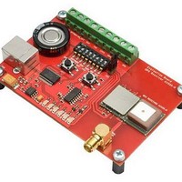
6.2 DIP Switch Settings
The following picture shows the DIP switches of the EVA1035-H.
*1: S7 has to be OFF to use an external VBAK supply.
*2: The BOOT switch can be set to flash Firmware to the A1035-H GPS re-
Switch
S1
S2
S3
S4
S5
S6
S7
S8
S7 has to be ON to use the onboard Supercap.
ceiver. Switch the BOOTSEL switch to “ON”, press and release the nRST
button. The A1035-H is now waiting to receive new firmware data via UART.
After upgrading the firmware switch the BOOTSEL switch to “OFF” and press
and release the nRST button for restarting normal GPS receiver operation.
Related software tool and documentation: SIRF_Flash
Function
BOOTSEL
RFPWUP
ON_OFF
RX0
TX0
ANT_SW
VBAK
VCC
Operation via USB connector
(default settings)
OFF
ON
ON
ON
ON
ON = high (A1035-H pin 8,
OFF = low (A1035-H on-module antenna)
ON
ON
Table 3: Switch settings
Figure 9: DIP switches
external active antenna)
User’s Manual
Operation via
terminal block
OFF (*2)
OFF
OFF
OFF
OFF
not applicable
OFF (*1)
OFF
Page 13 of 18
Related parts for V23993-EVA1035-H
Image
Part Number
Description
Manufacturer
Datasheet
Request
R

Part Number:
Description:
GPS Modules & Development Tools GPS Demo/Eval kit for A1037-A Module
Manufacturer:
VINCOTECH
Part Number:
Description:
GPS Modules & Development Tools GPS Demo Kit for A1035-C Module
Manufacturer:
VINCOTECH
Datasheet:
Part Number:
Description:
GPS Modules & Development Tools USB DEMO KIT
Manufacturer:
VINCOTECH
Part Number:
Description:
GPS Modules & Development Tools GPS Receiver Module Full NMEA (SMD)
Manufacturer:
VINCOTECH
Datasheet:

Part Number:
Description:
GPS Modules & Development Tools A2100-A SiRFStarIV GPS Eval Kit
Manufacturer:
VINCOTECH

Part Number:
Description:
GPS Modules & Development Tools A2100-A SiRFStarIV GPS recvr mod (3.3V)
Manufacturer:
VINCOTECH

Part Number:
Description:
GPS Modules & Development Tools A1082A SiRF GSCi5000 Receiver module
Manufacturer:
VINCOTECH
Datasheet:
Part Number:
Description:
GPS Modules & Development Tools GPS Demo/Eval kit for A1080-A Module
Manufacturer:
VINCOTECH
Datasheet:

Part Number:
Description:
GPS Modules & Development Tools A1084-B GPS Eval Kit
Manufacturer:
VINCOTECH
Datasheet:
Part Number:
Description:
GPS Modules & Development Tools GPS Receiver Module with TXCO (SMD)
Manufacturer:
VINCOTECH
Datasheet:
Part Number:
Description:
GPS Modules & Development Tools GPS Demo Kit for A1029-D Module
Manufacturer:
VINCOTECH
Part Number:
Description:
GPS Modules & Development Tools GPS Receiver Module w/Smart Antenna
Manufacturer:
VINCOTECH
Part Number:
Description:
GPS Modules & Development Tools GPS Receiver Module Full NMEA Ext Temp
Manufacturer:
VINCOTECH
Datasheet:
Part Number:
Description:
GPS Modules & Development Tools GPS Demo Kit (USB) for A1029-C Module
Manufacturer:
VINCOTECH
Part Number:
Description:
Standard Power Integrated Module
Manufacturer:
Vincotech
Datasheet: