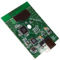
DLP-RF1-Z DLP Design Inc, DLP-RF1-Z Datasheet - Page 2

DLP-RF1-Z
Manufacturer Part Number
DLP-RF1-Z
Description
Zigbee / 802.15.4 Modules & Development Tools PC INTERFACE HOST MODULE (USB)
Manufacturer
DLP Design Inc
Datasheet
1.DLP-RF1-Z-G.pdf
(10 pages)
Specifications of DLP-RF1-Z
Wireless Frequency
2.4 GHz
Interface Type
USB
Operating Voltage
9 V
Antenna
Integral to PCB Design?No External
For Use With/related Products
MC13193, MC9S08GT60
Lead Free Status / RoHS Status
Lead free / RoHS Compliant
1.0 System Overview
Using the pre-programmed SIPP firmware, the DLP-RF1 can be used in conjunction with other DLP-RF1
and/or DLP-RF2 modules to form simple point-to-point and star configuration systems. Both the
DLP-RF1 and the DLP-RF2 can serve as host/system controllers. In the case of the DLP-RF1, the host
is a user-supplied Windows, Linux, or Mac PC that is accessed via a USB interface and user-supplied,
6-foot USB cable. In the case of the DLP-RF2, the host is a user-supplied microcontroller/
DSP/FPGA/etc. that is accessed via a 2-wire serial interface–TX, RX, and ground. A host processor is
not necessarily required by the DLP-RF2. The SIPP firmware within the DLP-RF2 can be used to both
gain access to the MC9S08GT60’s port pins for basic digital I/O as well as offer a few hardware-specific
functions.
The DLP-RF1 can be used in conjunction with other DLP-RF1/DLP-RF2 transceivers as well as other
MC13193-based transceivers to form complex point-to-point and star networks.
In a system using the preprogrammed SIPP firmware, each transceiver has a unique 16-bit ID yielding a
theoretical maximum of 65,535 transceivers. Every data packet handled by the SIPP firmware must
contain, at minimum, the number of bytes in the packet, the destination transceiver ID (packet destina-
tion), the source transceiver ID (packet origin), and a command byte.
As shipped from DLP Design, the DLP-RF1 has an ID of 1. If more than one DLP-RF1 is to be used in a
system, then this ID must be changed to a value higher than 2 (the DLP-RF2 has a default ID value of 2).
Upon reset or power up, the ID is read from non-volatile (EEPROM) memory. If JP1 is shorted at power
up (or before a reset), the default ID for the DLP-RF1 is set to 1, and other transceiver settings are also
returned to a default state in the EEPROM. (Refer to Section 2.2 for additional details.)
2.0 Preprogrammed Serial Interface Packet Processor (SIPP) Firmware
The source code for Freescale’s SMAC is available as a free download from www.freescale.com. The
SIPP firmware is based on the SMAC.
A test program (DLP-RFTestAp.exe) is available as a free download from
www.dlpdesign.com
that
makes easy work of setting up the DLP-RF1 transceiver and testing its basic functionality. Use of the
DLP-RFTestAp.exe requires a USB interface between a host Windows PC and the DLP-RF1 as well as a
user-supplied 6-foot USB cable.
**Under this communication protocol, it is the responsibility of the host application to “Retry”
transmissions that do not produce the anticipated reply.**
DLP-RF1/Z DLP Design, Inc.
2
Rev 1.5 (November 2005)


