AD565ATD Analog Devices Inc, AD565ATD Datasheet - Page 10
AD565ATD
Manufacturer Part Number
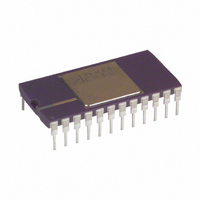
AD565ATD
Description
IC,D/A CONVERTER,SINGLE,12-BIT,BIPOLAR,DIP,24PIN
Manufacturer
Analog Devices Inc
Datasheet
1.AD565AJRZ-REEL.pdf
(12 pages)
Specifications of AD565ATD
Rohs Status
RoHS non-compliant
Settling Time
250ns
Number Of Bits
12
Data Interface
Parallel
Number Of Converters
1
Voltage Supply Source
Single Supply
Power Dissipation (max)
345mW
Operating Temperature
-55°C ~ 125°C
Mounting Type
Through Hole
Package / Case
24-CDIP (0.600", 15.24mm)
Lead Free Status / RoHS Status
Available stocks
Company
Part Number
Manufacturer
Quantity
Price

Part Number:
AD565ATD
Manufacturer:
ADI/亚德诺
Quantity:
20 000
Part Number:
AD565ATD/883
Manufacturer:
ADI/亚德诺
Quantity:
20 000


AD565A/AD566A
FIGURE 6. OTHER VOLTAGE RANGES
The AD566A can also be easily configured for a unipolar 0 V to
+5 V range or ± 2.5 V and ± 10 V bipolar ranges by using the
additional 5 kΩ application resistor provided at the 20 V span R
terminal, Pin 11. For a 5 V span (0 V to +5 V or ± 2.5 V), the two
5 kΩ resistors are used in parallel by shorting Pin 11 to Pin 9 and
connecting Pin 10 to the op amp output and the bipolar offset
resistor either to ground for unipolar or to V
range. For the ±10 V range (20 V span), use the 5 kΩ resistors in
series by connecting only Pin 11 to the op amp output and the
bipolar offset connected as shown. The ± 10 V option is shown
in Figure 6.
DIGITAL INPUT
MSB
0 0 0 0 0 0 0 0 0 0 0 0
0 1 1 1 1 1 1 1 1 1 1 1
1 0 0 0 0 0 0 0 0 0 0 0
1 1 1 1 1 1 1 1 1 1 1 1
*Inverts the MSB of the offset binary code with an external inverter to obtain twos complement.
LSB
Straight Binary
Zero
Mid Scale – 1 LSB
+1/2 FS
+FS – l LSB
REF
for the bipolar
Table I. Digital Input Codes
–10–
–V
ANALOG OUTPUT
Offset Binary
–FS
Zero – 1 LSB
Zero
+FS – 1 LSB
7.5V
14k
E
AD561
*
THE PARALLEL COMBINATION OF THE BIPOLAR OFFSET RESISTOR
AND R3 ESTABLISHES A CURRENT TO BALANCE THE MSB CURRENT.
THE EFFECT OF TEMPERATURE COEFFICIENT MISMATCH BETWEEN
THE BIPOLAR RESISTOR COMBINATION AND DAC RESISTORS IS
EXPANDED ON PREVIOUS PAGE.
REF
GND
5k
REF
R2
Figure 6. ± 10 V Voltage Output
REF
IN
–V
20k
AD566A
EE
19.95k
POWER
GND
0.5mA
I
REF
9.95k
5k
R1
MSB
Twos Complement*
Zero
+FS – 1 LSB
–FS
Zero – 1 LSB
INPUT
CODE
I
4
OUT
DAC
BIPOLAR OFF
5k
5k
CODE
I
REF
=
I
LSB
O
8k
DAC
OUT
10V SPAN
20V SPAN
2.4k
26k *
AD509
R3
10pF
REV.E
Related parts for AD565ATD
Image
Part Number
Description
Manufacturer
Datasheet
Request
R

Part Number:
Description:
±1.7g Dual-Axis IMEMS Accelerometer Evaluation Board
Manufacturer:
Analog Devices Inc
Datasheet:

Part Number:
Description:
Inertial Sensor Evaluation System
Manufacturer:
Analog Devices Inc
Datasheet:
Part Number:
Description:
Manufacturer:
Analog Devices Inc
Datasheet:
Part Number:
Description:
Manufacturer:
Analog Devices Inc
Datasheet:
Part Number:
Description:
Manufacturer:
Analog Devices Inc
Datasheet:
Part Number:
Description:
Manufacturer:
Analog Devices Inc
Datasheet:
Part Number:
Description:
Manufacturer:
Analog Devices Inc
Datasheet:
Part Number:
Description:
Manufacturer:
Analog Devices Inc
Datasheet:
Part Number:
Description:
Manufacturer:
Analog Devices Inc
Datasheet:
Part Number:
Description:
Manufacturer:
Analog Devices Inc
Datasheet:
Part Number:
Description:
Manufacturer:
Analog Devices Inc
Datasheet:
Part Number:
Description:
Manufacturer:
Analog Devices Inc
Datasheet:
Part Number:
Description:
Manufacturer:
Analog Devices Inc
Datasheet: