AD565ATD Analog Devices Inc, AD565ATD Datasheet - Page 9
AD565ATD
Manufacturer Part Number
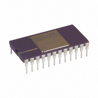
AD565ATD
Description
IC,D/A CONVERTER,SINGLE,12-BIT,BIPOLAR,DIP,24PIN
Manufacturer
Analog Devices Inc
Datasheet
1.AD565AJRZ-REEL.pdf
(12 pages)
Specifications of AD565ATD
Rohs Status
RoHS non-compliant
Settling Time
250ns
Number Of Bits
12
Data Interface
Parallel
Number Of Converters
1
Voltage Supply Source
Single Supply
Power Dissipation (max)
345mW
Operating Temperature
-55°C ~ 125°C
Mounting Type
Through Hole
Package / Case
24-CDIP (0.600", 15.24mm)
Lead Free Status / RoHS Status
Available stocks
Company
Part Number
Manufacturer
Quantity
Price

Part Number:
AD565ATD
Manufacturer:
ADI/亚德诺
Quantity:
20 000
Part Number:
AD565ATD/883
Manufacturer:
ADI/亚德诺
Quantity:
20 000


CONNECTING THE AD566A FOR BUFFERED VOLTAGE
OUTPUT
The standard current-to-voltage conversion connections using an
operational amplifier are shown in Figures 4, 5, and 6 with the
preferred trimming techniques. If a low offset operational amplifier
(OP77, AD741L, OP07) is used, excellent performance can be
obtained in many situations without trimming (an op amp with
less than 0.5 mV max offset voltage should be used to keep offset
errors below 1/2 LSB). If a 50 Ω fixed resistor is substituted for the
100 Ω trimmer, unipolar zero typically is within ±1/2 LSB (plus op
amp offset), and full-scale accuracy is within 0.1% (0.25% max).
Substituting a 50 Ω resistor for the 100 Ω bipolar offset trimmer
gives a bipolar zero error typically within ± 2 LSB (0.05%).
The AD509 is recommended for buffered voltage-output
applications that require a settling time to ± 1/2 LSB of 1 µs. The
feedback capacitor is shown with the optimum value for each
application; this capacitor is required to compensate for the
25 pF DAC output capacitance.
FIGURE 4. UNIPOLAR CONFIGURATION
This configuration provides a unipolar 0 V to 10 V output range.
In this mode, the bipolar terminal, Pin 7, should be grounded if not
used for trimming.
STEP I . . . ZERO ADJUST
Turn all bits OFF and adjust zero trimmer, R1, until the output
reads 0.000 V (1 LSB = 2.44 mV). In most cases, this trim is
not needed, but Pin 7 should then be connected to Pin 12.
REV. E
+V
100
10V
R2
Figure 4. 0 V to 10 V Unipolar Voltage Output
E
AD561
REF
GND
REF
REF
IN
–V
20k
AD566A
19.95k
EE
POWER
GND
0.5mA
I
REF
9.95k
100
MSB
INPUT
CODE
I
4
OUT
DAC
BIPOLAR OFF
5k
5k
CODE
I
REF
=
I
LSB
O
8k
100k
DAC
OUT
20V SPAN
10V SPAN
+15V
–15V
R1
50k
2.4k
AD509
10pF
–9–
STEP II . . . GAIN ADJUST
Turn all bits ON and adjust 100 Ω gain trimmer, R2, until the
output is 9.9976 V. (Full scale is adjusted to 1 LSB less than
nominal full scale of 10.000 V.) If a 10.2375 V full scale is desired
(exactly 2.5 mV/bit), insert a 120 Ω resistor in series with the
gain resistor at Pin 10 to the op amp output.
FIGURE 5. BIPOLAR CONFIGURATION
This configuration provides a bipolar output voltage from
–5.000 V to +4.9976 V, with positive full scale occurring with
all bits ON (all 1s).
STEP I . . . OFFSET ADJUST
Turn OFF all bits. Adjust 100 Ω trimmer R1 to give –5.000
output V.
STEP II . . . GAIN ADJUST
Turn ON all bits. Adjust 100 Ω gain trimmer R2 to give a read-
ing of +4.9976 V.
Please note that it is not necessary to trim the op amp to obtain
full accuracy at room temperature. In most bipolar situations,
an op amp trim is unnecessary unless the untrimmed offset drift
of the op amp is excessive.
+V
10V
100
E
AD561
R2
REF
GND
REF
Figure 5. ± 5 V Bipolar Voltage Output
REF
IN
–V
20k
AD566A
19.95k
EE
POWER
GND
100
R1
0.5mA
I
REF
9.95k
MSB
AD565A/AD566A
CODE
INPUT
I
4
OUT
DAC
BIPOLAR OFF
5k
CODE
5k
I
REF
=
I
LSB
O
8k
DAC
OUT
20V SPAN
10V SPAN
2.4k
AD509
10pF
Related parts for AD565ATD
Image
Part Number
Description
Manufacturer
Datasheet
Request
R

Part Number:
Description:
±1.7g Dual-Axis IMEMS Accelerometer Evaluation Board
Manufacturer:
Analog Devices Inc
Datasheet:

Part Number:
Description:
Inertial Sensor Evaluation System
Manufacturer:
Analog Devices Inc
Datasheet:
Part Number:
Description:
Manufacturer:
Analog Devices Inc
Datasheet:
Part Number:
Description:
Manufacturer:
Analog Devices Inc
Datasheet:
Part Number:
Description:
Manufacturer:
Analog Devices Inc
Datasheet:
Part Number:
Description:
Manufacturer:
Analog Devices Inc
Datasheet:
Part Number:
Description:
Manufacturer:
Analog Devices Inc
Datasheet:
Part Number:
Description:
Manufacturer:
Analog Devices Inc
Datasheet:
Part Number:
Description:
Manufacturer:
Analog Devices Inc
Datasheet:
Part Number:
Description:
Manufacturer:
Analog Devices Inc
Datasheet:
Part Number:
Description:
Manufacturer:
Analog Devices Inc
Datasheet:
Part Number:
Description:
Manufacturer:
Analog Devices Inc
Datasheet:
Part Number:
Description:
Manufacturer:
Analog Devices Inc
Datasheet: