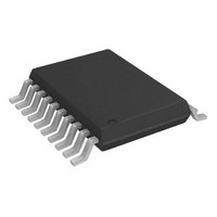
AD7998BRU-0 Analog Devices Inc, AD7998BRU-0 Datasheet - Page 17

AD7998BRU-0
Manufacturer Part Number
AD7998BRU-0
Description
IC,Data Acquisition System,8-CHANNEL,12-BIT,TSSOP,20PIN,PLASTIC
Manufacturer
Analog Devices Inc
Datasheet
1.AD7997BRUZ-1.pdf
(32 pages)
Specifications of AD7998BRU-0
Number Of Bits
12
Sampling Rate (per Second)
188k
Data Interface
I²C, Serial
Number Of Converters
1
Power Dissipation (max)
2.2mW
Voltage Supply Source
Single Supply
Operating Temperature
-40°C ~ 85°C
Mounting Type
Surface Mount
Package / Case
20-TSSOP (0.173", 4.40mm Width)
Lead Free Status / RoHS Status
Contains lead / RoHS non-compliant
For Use With
EVAL-AD7998CBZ - BOARD EVALUATION FOR AD7998CBZ
Lead Free Status / RoHS Status
Contains lead / RoHS non-compliant, Contains lead / RoHS non-compliant
For ac applications, removing high frequency components from
the analog input signal is recommended, by using an RC band-
pass filter on the relevant analog input pin. In applications where
harmonic distortion and signal-to-noise ratio are critical, the
analog input should be driven from a low impedance source.
Large source impedances significantly affect the ac performance
of the ADC. This may necessitate the use of an input buffer
amplifier. The choice of the op amp is a function of the particular
application.
When no amplifier is used to drive the analog input, the source
impedance should be limited to low values. The maximum source
impedance depends on the amount of total harmonic distortion
(THD) that can be tolerated. THD increases as the source imped-
ance increases, and performance degrades. Figure 23 shows the
THD vs. the analog input signal frequency when using supply
voltages of 3 V ± 10% and 5 V ± 10%. Figure 24 shows the THD
vs. the analog input signal frequency for different source
impedances.
Rev. 0 | Page 17 of 32
–100
–60
–100
–40
–50
–70
–80
–90
–60
–40
–50
–70
–80
–90
10
10
Figure 23. THD vs. Analog Input Frequency for Various
Figure 24. THD vs. Analog Input Frequency for Various
Source Impedances for V
V
DD
= 2.7V
Supply Voltages, F
INPUT FREQUENCY (kHz)
INPUT FREQUENCY (kHz)
V
V
DD
100
DD
100
S
DD
= 5V
= 136 kSPS, Mode 1
= 4.5V
R
R
= 5 V, 136 kSPS, Mode 1
IN
V
IN
DD
R
= 1000 Ω
= 100 Ω
IN
= 3V
= 10 Ω
AD7997/AD7998
V
DD
V
DD
= 3.3V
= 5.5V
R
IN
V
= 50 Ω
DD
= 5V
1000
1000


