AD9230-250EBZ Analog Devices Inc, AD9230-250EBZ Datasheet - Page 27
AD9230-250EBZ
Manufacturer Part Number
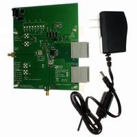
AD9230-250EBZ
Description
12-Bit 250 Msps ADC EB
Manufacturer
Analog Devices Inc
Datasheet
1.AD9230BCPZ-170.pdf
(32 pages)
Specifications of AD9230-250EBZ
Number Of Adc's
1
Number Of Bits
12
Sampling Rate (per Second)
250M
Data Interface
Serial
Inputs Per Adc
1 Single Ended
Input Range
1.0 ~ 1.5 V
Power (typ) @ Conditions
434mW @ 250MSPS
Voltage Supply Source
Single Supply
Operating Temperature
-40°C ~ 85°C
Utilized Ic / Part
AD9230
Lead Free Status / RoHS Status
Lead free / RoHS Compliant
Lead Free Status / RoHS Status
Lead free / RoHS Compliant


MEMORY MAP
READING THE MEMORY MAP TABLE
Each row in the memory map table has eight address locations.
The memory map is roughly divided into three sections: chip
configuration register map (Address 0x00 to Address 0x02),
transfer register map (Address 0xFF), and program register map
(Address 0x08 to Address 0x2A).
The Addr. (Hex) column of the memory map indicates the
register address in hexadecimal, and the Default Value (Hex)
column shows the default hexadecimal value that is already
written into the register The Bit 7 (MSB) column is the start of
the default hexadecimal value given. For example, Hexadecimal
Address 0x09, clock, has a hexadecimal default value of 0x01.
This means Bit 7 = 0, Bit 6 = 0, Bit 5 = 0, Bit 4 = 0, Bit 3 = 0,
Bit 2 = 0, Bit 1 = 0, and Bit 0 = 1, or 0000 0001 in binary. The
default value enables the duty cycle stabilizer. Overwriting this
default so that Bit 0 = 0 disables the duty cycle stabilizer. For more
information on this and other functions, consult the Interfacing
to High-Speed ADCs via SPI® user manual at www.analog.com.
Table 13. Memory Map Register
Addr.
(Hex)
Chip Configuration Registers
00
01
02
Transfer Register
FF
Parameter Name
chip_port_config
chip_id
chip_grade
device_update
Bit 7
(MSB)
0
0
0
Bit 6
LSB
first
0
0
Bit 5
Soft
reset
0
0
Bit 4
1
0
8-bit chip ID, Bits[7:0]
Rev. 0 | Page 27 of 32
00 = 250 MSPS
01 = 210 MSPS
10 = 170 MSPS
AD9230 = 0x0C
Speed grade:
Bit 3
1
0
RESERVED LOCATIONS
Undefined memory locations should not be written to other
than their default values suggested in this data sheet. Addresses
that have values marked as 0 should be considered reserved and
have a 0 written into their registers during power-up.
DEFAULT VALUES
Coming out of reset, critical registers are preloaded with default
values. These values are indicated in Table 13. Other registers
do not have default values and retain the previous value when
exiting reset.
LOGIC LEVELS
An explanation of various registers follows: “Bit is set” is
synonymous with “bit is set to Logic 1” or “writing Logic 1 for
the bit. ” Similarly, “clear a bit” is synonymous with “bit is set to
Logic 0” or “writing Logic 0 for the bit. ”
Bit 2
Soft
reset
X
0
Bit 1
LSB first
X
0
Bit 0
(LSB)
0
X
SW
transfer
Default
Value
(Hex)
0x18
Read-
only
Read-
only
0x00
Default Notes/
Comments
The nibbles
should be
mirrored by the
user so that LSB
or MSB first
mode registers
correctly,
regardless of
shift mode.
Default is unique
chip ID, different
for each device.
This is a read-
only register.
Child ID used to
differentiate
graded devices.
Synchronously
transfers data
from the master
shift register to
the slave.
AD9230
Related parts for AD9230-250EBZ
Image
Part Number
Description
Manufacturer
Datasheet
Request
R

Part Number:
Description:
12-Bit 170 Msps ADC EB
Manufacturer:
Analog Devices Inc
Datasheet:
Part Number:
Description:
12-Bit 210 Msps ADC EB
Manufacturer:
Analog Devices Inc
Datasheet:

Part Number:
Description:
±1.7g Dual-Axis IMEMS Accelerometer Evaluation Board
Manufacturer:
Analog Devices Inc
Datasheet:
Part Number:
Description:
Inertial Sensor Evaluation System
Manufacturer:
Analog Devices Inc
Datasheet:
Part Number:
Description:
Manufacturer:
Analog Devices Inc
Datasheet:
Part Number:
Description:
Manufacturer:
Analog Devices Inc
Datasheet:
Part Number:
Description:
Manufacturer:
Analog Devices Inc
Datasheet:
Part Number:
Description:
Manufacturer:
Analog Devices Inc
Datasheet:
Part Number:
Description:
Manufacturer:
Analog Devices Inc
Datasheet:
Part Number:
Description:
Manufacturer:
Analog Devices Inc
Datasheet:
Part Number:
Description:
Manufacturer:
Analog Devices Inc
Datasheet:
Part Number:
Description:
Manufacturer:
Analog Devices Inc
Datasheet:
Part Number:
Description:
Manufacturer:
Analog Devices Inc
Datasheet: