ADXL345BCCZ-RL Analog Devices Inc, ADXL345BCCZ-RL Datasheet - Page 30
ADXL345BCCZ-RL
Manufacturer Part Number
ADXL345BCCZ-RL
Description
Digital Output Three-Axis Accel 4K RL
Manufacturer
Analog Devices Inc
Series
iMEMS®r
Datasheet
1.EVAL-ADXL345Z.pdf
(40 pages)
Specifications of ADXL345BCCZ-RL
Design Resources
Sensing Low-g Acceleration Using ADXL345 Digital Accelerometer Connected to ADuC7024 (CN0133)
Axis
X, Y, Z
Acceleration Range
±2g, 4g, 8g, 16g
Sensitivity
256LSB/g, 128LSB/g, 64LSB/g, 32LSB/g
Voltage - Supply
2 V ~ 3.6 V
Output Type
Digital
Bandwidth
6.25Hz ~ 3.2kHz Selectable
Interface
I²C, SPI
Mounting Type
Surface Mount
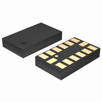
Package / Case
14-LGA
Package Type
LGA
Operating Supply Voltage (typ)
2.5V
Operating Supply Voltage (max)
3.6V
Operating Temperature (min)
-40C
Operating Temperature (max)
85C
Operating Temperature Classification
Industrial
Product Depth (mm)
3mm
Product Length (mm)
5mm
Mounting
Surface Mount
Pin Count
14
Lead Free Status / RoHS Status
Lead free / RoHS Compliant
Lead Free Status / RoHS Status
Lead free / RoHS Compliant
Other names
ADXL345BCCZ-RLTR
Available stocks
Company
Part Number
Manufacturer
Quantity
Price
Company:

Part Number:
ADXL345BCCZ-RL7
Manufacturer:
POWER
Quantity:
14 300


ADXL345
SLEEP MODE VS. LOW POWER MODE
In applications where a low data rate and low power consumption
is desired (at the expense of noise performance), it is recommended
that low power mode be used. The use of low power mode preserves
the functionality of the DATA_READY interrupt and the FIFO
for postprocessing of the acceleration data. Sleep mode, while
offering a low data rate and power consumption, is not intended
for data acquisition.
However, when sleep mode is used in conjunction with the
AUTO_SLEEP mode and the link mode, the part can automatically
switch to a low power, low sampling rate mode when inactivity
is detected. To prevent the generation of redundant inactivity
interrupts, the inactivity interrupt is automatically disabled
and activity is enabled. When the ADXL345 is in sleep mode, the
host processor can also be placed into sleep mode or low power
mode to save significant system power. When activity is detected,
the accelerometer automatically switches back to the original
data rate of the application and provides an activity interrupt
that can be used to wake up the host processor. Similar to when
inactivity occurs, detection of activity events is disabled and
inactivity is enabled.
OFFSET CALIBRATION
Accelerometers are mechanical structures containing elements
that are free to move. These moving parts can be very sensitive
to mechanical stresses, much more so than solid-state electronics.
The 0 g bias or offset is an important accelerometer metric because
it defines the baseline for measuring acceleration. Additional
stresses can be applied during assembly of a system containing
an accelerometer. These stresses can come from, but are not
limited to, component soldering, board stress during mounting,
and application of any compounds on or over the component. If
calibration is deemed necessary, it is recommended that calibration
be performed after system assembly to compensate for these effects.
A simple method of calibration is to measure the offset while
assuming that the sensitivity of the ADXL345 is as specified in
Table 1. The offset can then be automatically accounted for by
using the built-in offset registers. This results in the data acquired
from the DATA registers already compensating for any offset.
In a no-turn or single-point calibration scheme, the part is oriented
such that one axis, typically the z-axis, is in the 1 g field of gravity
and the remaining axes, typically the x- and y-axis, are in a 0 g
field. The output is then measured by taking the average of a
series of samples. The number of samples averaged is a choice of
the system designer, but a recommended starting point is 0.1 sec
worth of data for data rates of 100 Hz or greater. This corresponds
to 10 samples at the 100 Hz data rate. For data rates less than
100 Hz, it is recommended that at least 10 samples be averaged
together. These values are stored as X
measurements on the x- and y-axis and the 1 g measurement on
the z-axis, respectively.
0g
, Y
0g
, and Z
+1g
for the 0 g
Rev. B | Page 30 of 40
The values measured for X
offset, and compensation is done by subtracting those values from
the output of the accelerometer to obtain the actual acceleration:
Because the z-axis measurement was done in a +1 g field, a no-turn
or single-point calibration scheme assumes an ideal sensitivity,
S
offset, which is then subtracted from future measured values to
obtain the actual value:
The ADXL345 can automatically compensate the output for offset
by using the offset registers (Register 0x1E, Register 0x1F, and
Register 0x20). These registers contain an 8-bit, twos complement
value that is automatically added to all measured acceleration
values, and the result is then placed into the DATA registers.
Because the value placed in an offset register is additive, a negative
value is placed into the register to eliminate a positive offset and
vice versa for a negative offset. The register has a scale factor of
15.6 mg/LSB and is independent of the selected g-range.
As an example, assume that the ADXL345 is placed into full-
resolution mode with a sensitivity of typically 256 LSB/g. The
part is oriented such that the z-axis is in the field of gravity and
x-, y-, and z-axis outputs are measured as +10 LSB, −13 LSB,
and +9 LSB, respectively. Using the previous equations, X
+10 LSB, Y
in full-resolution is 3.9 mg or one-quarter of an LSB of the
offset register. Because the offset register is additive, the 0 g
values are negated and rounded to the nearest LSB of the offset
register:
These values are programmed into the OFSX, OFSY, and OFXZ
registers, respectively, as 0xFD, 0x03 and 0xFE. As with all
registers in the ADXL345, the offset registers do not retain the
value written into them when power is removed from the part.
Power-cycling the ADXL345 returns the offset registers to their
default value of 0x00.
Because the no-turn or single-point calibration method assumes an
ideal sensitivity in the z-axis, any error in the sensitivity results in
offset error. For instance, if the actual sensitivity was 250 LSB/g
in the previous example, the offset would be 15 LSB, not 9 LSB.
To help minimize this error, an additional measurement point
can be used with the z-axis in a 0 g field and the 0 g measurement
can be used in the Z
Z
for the z-axis. This is subtracted from Z
X
Y
Z
Z
X
Y
Z
ACTUAL
0g
ACTUAL
OFFSET
OFFSET
ACTUAL
OFFSET
= Z
0g
+1g
= −Round(−13/4) = 3 LSB
= −Round(9/4) = −2 LSB
= −Round(10/4) = −3 LSB
= Y
= Z
= X
is −13 LSB, and Z
− S
MEAS
MEAS
MEAS
Z
− Y
− Z
ACTUAL
− X
0g
0g
0g
0g
equation.
and Y
0g
is +9 LSB. Each LSB of output
0g
correspond to the x- and y-axis
+1g
to attain the z-axis
0g
is
Related parts for ADXL345BCCZ-RL
Image
Part Number
Description
Manufacturer
Datasheet
Request
R

Part Number:
Description:
±1.7g Dual-Axis IMEMS Accelerometer Evaluation Board
Manufacturer:
Analog Devices Inc
Datasheet:

Part Number:
Description:
Inertial Sensor Evaluation System
Manufacturer:
Analog Devices Inc
Datasheet:
Part Number:
Description:
Manufacturer:
Analog Devices Inc
Datasheet:
Part Number:
Description:
Manufacturer:
Analog Devices Inc
Datasheet:
Part Number:
Description:
Manufacturer:
Analog Devices Inc
Datasheet:
Part Number:
Description:
Manufacturer:
Analog Devices Inc
Datasheet:
Part Number:
Description:
Manufacturer:
Analog Devices Inc
Datasheet:
Part Number:
Description:
Manufacturer:
Analog Devices Inc
Datasheet:
Part Number:
Description:
Manufacturer:
Analog Devices Inc
Datasheet:
Part Number:
Description:
Manufacturer:
Analog Devices Inc
Datasheet:
Part Number:
Description:
Manufacturer:
Analog Devices Inc
Datasheet:
Part Number:
Description:
Manufacturer:
Analog Devices Inc
Datasheet:
Part Number:
Description:
Manufacturer:
Analog Devices Inc
Datasheet: