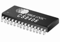
CS8406-CZZR Cirrus Logic Inc, CS8406-CZZR Datasheet - Page 2

CS8406-CZZR
Manufacturer Part Number
CS8406-CZZR
Description
IC,Digital Audio Transmitter,CMOS,TSSOP,28PIN,PLASTIC
Manufacturer
Cirrus Logic Inc
Type
Digital Audio Interface Transmitterr
Specifications of CS8406-CZZR
Applications
Automotive Audio
Mounting Type
Surface Mount
Package / Case
28-TSSOP
Lead Free Status / RoHS Status
Lead free / RoHS Compliant
For Use With
598-1017 - BOARD EVAL FOR CS8416 RCVR
Lead Free Status / RoHS Status
Lead free / RoHS Compliant
Other names
Q4266681
Available stocks
Company
Part Number
Manufacturer
Quantity
Price
Company:
Part Number:
CS8406-CZZR
Manufacturer:
KINGBRIGHT
Quantity:
2 000
2
TABLE OF CONTENTS
1. CHARACTERISTICS AND SPECIFICATIONS ..................................................................................... 4
2. TYPICAL CONNECTION DIAGRAMS .................................................................................................. 9
3. GENERAL DESCRIPTION .................................................................................................................. 11
4. THREE-WIRE SERIAL INPUT AUDIO PORT ..................................................................................... 12
5. AES3 TRANSMITTER ......................................................................................................................... 13
6. CONTROL PORT DESCRIPTION ....................................................................................................... 16
7. CONTROL PORT REGISTER SUMMARY ......................................................................................... 18
8. CONTROL PORT REGISTER BIT DEFINITIONS .............................................................................. 19
9. PIN DESCRIPTION - SOFTWARE MODE
10. HARDWARE MODE .......................................................................................................................... 27
11. PIN DESCRIPTION - HARDWARE MODE ....................................................................................... 29
12. APPLICATIONS ................................................................................................................................ 31
13. PACKAGE DIMENSIONS ................................................................................................................ 32
14. ORDERING INFORMATION ............................................................................................................. 34
SPECIFIED OPERATING CONDITIONS .............................................................................................. 4
ABSOLUTE MAXIMUM RATINGS ........................................................................................................ 4
DC ELECTRICAL CHARACTERISTICS ............................................................................................... 4
DIGITAL INPUT CHARACTERISTICS .................................................................................................. 5
DIGITAL INTERFACE SPECIFICATIONS ............................................................................................ 5
TRANSMITTER CHARACTERISTICS .................................................................................................. 5
SWITCHING CHARACTERISTICS ....................................................................................................... 5
SWITCHING CHARACTERISTICS - SERIAL AUDIO PORTS ............................................................. 6
SWITCHING CHARACTERISTICS - CONTROL PORT - SPI MODE................................................... 7
SWITCHING CHARACTERISTICS - CONTROL PORT - I²C MODE.................................................... 8
3.1 AES3 and S/PDIF Standards Documents .................................................................................... 11
5.1 TXN and TXP Drivers ................................................................................................................... 13
5.2 Mono Mode Operation .................................................................................................................. 13
5.3 Transmitted Frame and Channel Status Boundary Timing ........................................................... 13
6.1 SPI Mode ...................................................................................................................................... 16
6.2 I²C Mode ....................................................................................................................................... 17
8.1 Memory Address Pointer (MAP) ................................................................................................... 19
8.2 Default = ‘000000’Control 1 (01h) ................................................................................................. 19
8.3 Control 2 (02h) .............................................................................................................................. 19
8.4 Data Flow Control (03h) ............................................................................................................... 20
8.5 Clock Source Control (04h) .......................................................................................................... 20
8.6 Serial Audio Input Port Data Format (05h) ................................................................................... 21
8.7 Interrupt 1 Status (07h) (Read Only) ............................................................................................ 22
8.8 Interrupt 2 Status (08h) (Read Only) ............................................................................................ 22
8.9 Interrupt 1 Mask (09h) .................................................................................................................. 22
8.10 Interrupt 1 Mode MSB (0Ah) and Interrupt 1 Mode LSB (0Bh) ................................................... 23
8.11 Interrupt 2 Mask (0Ch) ................................................................................................................ 23
8.12 Interrupt 2 Mode MSB (0Dh) and Interrupt Mode 2 LSB (0Eh) .................................................. 23
8.13 Channel Status Data Buffer Control (12h) .................................................................................. 23
8.14 User Data Buffer Control (13h) ................................................................................................... 24
8.15 Channel Status Bit or User Bit Data Buffer (20h - 37h) .............................................................. 24
8.16 CS8406 I.D. and Version Register (7Fh) (Read Only) ................................................................ 24
10.1 Channel Status, User and Validity Data ..................................................................................... 27
10.2 Serial Audio Port ......................................................................................................................... 28
12.1 Reset, Power Down and Start-Up .............................................................................................. 31
12.2 ID Code and Revision Code ....................................................................................................... 31
12.3 Power Supply, Grounding, and PCB layout ................................................................................ 31
12.4 Synchronization of Multiple CS8406s ......................................................................................... 31
....................................................................................... 25
CS8406
DS580F4


