DG406DN-T1-E3 Vishay, DG406DN-T1-E3 Datasheet - Page 10
DG406DN-T1-E3
Manufacturer Part Number
DG406DN-T1-E3
Description
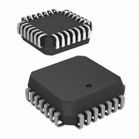
IC,ANALOG MUX,SINGLE,16-CHANNEL,CMOS,LDCC,28PIN,PLASTIC
Manufacturer
Vishay
Datasheet
1.DG406DN-T1-E3.pdf
(11 pages)
Specifications of DG406DN-T1-E3
Function
Multiplexer
Circuit
1 x 16:1
On-state Resistance
120 Ohm
Voltage Supply Source
Single, Dual Supply
Voltage - Supply, Single/dual (±)
12V, ±5 V ~ 20 V
Current - Supply
50µA
Operating Temperature
-40°C ~ 85°C
Mounting Type
Surface Mount
Package / Case
28-PLCC
Number Of Channels
16 Channel
On Resistance (max)
120 Ohms
Propagation Delay Time
350 ns
On Time (max)
600 ns
Off Time (max)
300 ns
Supply Voltage (max)
20 V
Supply Voltage (min)
5 V
Supply Current
0.05 mA
Maximum Power Dissipation
450 mW
Maximum Operating Temperature
+ 85 C
Minimum Operating Temperature
- 40 C
Mounting Style
SMD/SMT
Off State Leakage Current (max)
40 nA
Lead Free Status / RoHS Status
Lead free / RoHS Compliant
Lead Free Status / RoHS Status
Lead free / RoHS Compliant
Other names
DG406DN-T1-E3TR
Available stocks
Company
Part Number
Manufacturer
Quantity
Price
Company:

Part Number:
DG406DN-T1-E3
Manufacturer:
TI
Quantity:
114
Company:
Part Number:
DG406DN-T1-E3
Manufacturer:
Vishay Siliconix
Quantity:
10 000


DG406, DG407
Vishay Siliconix
APPLICATIONS HINTS
Sampling speed is limited by two consecutive events: the
transition time of the multiplexer, and the settling time of the
sampled signal at the output.
t
depends on several parameters: R
source impedance, multiplexer and load capacitances,
charge injection of the multiplexer and accuracy desired.
The settling time for the multiplexer alone can be derived
from the model shown in figure 5. Assuming a low
impedance signal source like that presented by an op amp or
a buffer amplifier, the settling time of the RC network for a
given accuracy is equal to n:
The maximum sampling frequency of the multiplexer is:
Vishay Siliconix maintains worldwide manufacturing capability. Products may be manufactured at one of several qualified locations. Reliability data for Silicon
Technology and Package Reliability represent a composite of all qualified locations. For related documents such as package/tape drawings, part marking, and
reliability data, see www.vishay.com/ppg?70061.
www.vishay.com
10
TRANS
f
s
=
Figure 5. Simplified Model of One Multiplexer Channel
N(t
% ACCURACY
where N = number of channels to scan
t
is given on the data sheet. Settling time at the load
SETTLING
SETTLING
0.0017
0.012
0.25
Figure 6. Measuring low-level analog signals is more accurate when using a differential multiplexing technique
1
R
S
+ t
= n = n x R
= 0
TRANS
Sensor 1
Sensor 8
To
To
R
)
DS(on)
DS(on)
# BITS
12
15
8
DS(on)
x C
C
D(on)
D(on)
V
of the multiplexer,
OUT
Multiplexer
DG407
Analog
11
N
6
9
(1)
Amp
Inst
For the DG406 then, at room temp and for 12-bit accuracy,
using the maximum limits:
or
f
From the sampling theorem, to properly recover the original
signal, the sampling frequency should be more than twice
the maximum component frequency of the original signal.
This assumes perfect bandlimiting. In a real application
sampling at three to four times the filter cutoff frequency is a
good practice.
Therefore from equation 2 above:
From this we can see that the DG406 can be used to sample
16 different signals whose maximum component frequency
can be as high as 173 kHz. If for example, two channels are
used to double sample the same incoming signal then its
cutoff frequency can be doubled.
The block diagram shown in Figure 6 illustrates a typical data
acquisition front end suitable for low-level analog signals.
Differential multiplexing of small signals is preferred since
this method helps to reject any common mode noise. This is
especially important when the sensors are located at a
distance and it may eliminate the need for individual
amplifiers. A low R
DG407 helps to reduce measurement errors. The low power
dissipation of the DG407 minimizes on-chip thermal
gradients which can cause errors due to temperature
mismatch along the parasitic thermocouple paths. Please
refer to Application Note AN203 for additional information.
f
s
f
s
c
= 694 kHz
Controller
=
=
16 (9 x 100 Ω x 10
1
4
x f
s
S/H
= 173 kHz
DS(on)
Converter
12-Bit
1
-12
A/D
, low leakage multiplexer like the
F) + 300 x 10
S11-0179-Rev. J, 07-Feb-11
Document Number: 70061
-12
s
(2)
(3)
(4)
Related parts for DG406DN-T1-E3
Image
Part Number
Description
Manufacturer
Datasheet
Request
R

Part Number:
Description:
Analog Multiplexer Single 16:1 28-Pin PLCC
Manufacturer:
Vishay
Datasheet:

Part Number:
Description:
Multiplexer Switch ICs Single 16:1, 4-bit Multiplexer/MUX
Manufacturer:
Vishay
Datasheet:

Part Number:
Description:
Maxim's redesigned DG406 and DG407 CMOS analog multiplexers now feature guaranteed matching between channels (8Ω max) and flatness over the specified signal range (9Ω max)
Manufacturer:
Maxim
Datasheet:
Part Number:
Description:
Single 16-Channel/Differential 8-Channel CMOS Analog Multiplexers
Manufacturer:
INTERSIL [Intersil Corporation]
Datasheet:

Part Number:
Description:
DG406 Multiplexer Optimizes Medical Simulator
Manufacturer:
Vishay Semiconductors
Datasheet:
Part Number:
Description:
357-036-542-201 CARDEDGE 36POS DL .156 BLK LOPRO
Manufacturer:
Vishay
Datasheet:
Part Number:
Description:
357-036-542-201 CARDEDGE 36POS DL .156 BLK LOPRO
Manufacturer:
Vishay
Datasheet:
Part Number:
Description:
357-036-542-201 CARDEDGE 36POS DL .156 BLK LOPRO
Manufacturer:
Vishay
Datasheet:
Part Number:
Description:
357-036-542-201 CARDEDGE 36POS DL .156 BLK LOPRO
Manufacturer:
Vishay
Datasheet:
Part Number:
Description:
357-036-542-201 CARDEDGE 36POS DL .156 BLK LOPRO
Manufacturer:
Vishay
Datasheet:
Part Number:
Description:
357-036-542-201 CARDEDGE 36POS DL .156 BLK LOPRO
Manufacturer:
Vishay
Datasheet:
Part Number:
Description:
357-036-542-201 CARDEDGE 36POS DL .156 BLK LOPRO
Manufacturer:
Vishay
Datasheet:
Part Number:
Description:
357-036-542-201 CARDEDGE 36POS DL .156 BLK LOPRO
Manufacturer:
Vishay
Datasheet:
Part Number:
Description:
357-036-542-201 CARDEDGE 36POS DL .156 BLK LOPRO
Manufacturer:
Vishay
Datasheet: