EVAL-ADF7021-NDBZ5 Analog Devices Inc, EVAL-ADF7021-NDBZ5 Datasheet - Page 58
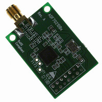
EVAL-ADF7021-NDBZ5
Manufacturer Part Number
EVAL-ADF7021-NDBZ5
Description
Matching Unpopulated
Manufacturer
Analog Devices Inc
Type
Transceiver, FSKr
Datasheet
1.ADF7021-NBCPZ-RL.pdf
(64 pages)
Specifications of EVAL-ADF7021-NDBZ5
Frequency
80MHz ~ 650MHz
Lead Free Status / RoHS Status
Lead free / RoHS Compliant
For Use With/related Products
ADF7021-N
Lead Free Status / Rohs Status
Supplier Unconfirmed


ADF7021-N
REGISTER 9—AGC REGISTER
•
•
ML1
0
1
It is necessary to program this register only if AGC
settings, other than the defaults, are required.
In receive mode, AGC is set to automatic AGC by default
on power-up. The default thresholds are AGC_ LOW_
THRESHOLD = 30 and AGC_HIGH_ THRESHOLD = 70.
See the RSSI/AGC section for details.
LI2
0
MIXER_LINEARITY
DEFAULT
HIGH
LI1
0
LNA_BIAS
800µA (DEFAULT)
LG1
0
1
LNA_MODE
DEFAULT
REDUCED GAIN
FI1
0
1
FG2
0
0
1
1
FILTER_CURRENT
LOW
HIGH
FG1 FILTER_GAIN
0
1
0
1
8
24
72
INVALID
FILTER_
GAIN
LG2
0
0
1
1
GAIN
LG1
0
1
0
1
LNA_
Figure 72. Register 9—AGC Register Map
LNA_GAIN
3
10
30
INVALID
MODE
0
1
2
3
AGC_
AGC_MODE
AUTO AGC
MANUAL AGC
FREEZE AGC
RESERVED
Rev. 0 | Page 58 of 64
AGC_HIGH_THRESHOLD
GH7
0
0
0
0
.
.
.
1
1
1
•
•
GH6
0
0
0
0
.
.
.
0
0
0
AGC high and low settings must be more than 30 apart to
ensure correct operation.
An LNA gain of 30 is available only if LNA_MODE
(R9_DB25) is set to 0.
GL7
0
0
0
0
.
.
.
1
1
1
GH5
0
0
0
0
.
.
.
0
0
1
GL6
0
0
0
0
.
.
.
1
1
1
GH4
0
0
0
0
.
.
.
1
1
0
GL5
0
0
0
0
.
.
.
1
1
1
GH3
0
0
0
1
.
.
.
1
1
0
AGC_LOW_THRESHOLD
GL4
0
0
0
0
.
.
.
1
1
1
GH2
0
1
1
0
.
.
.
1
1
0
GL3
0
0
0
1
.
.
.
1
1
1
GH1
1
0
1
0
.
.
.
0
1
0
GL2
0
1
1
0
.
.
.
0
1
1
AGC_HIGH_
THRESHOLD
1
2
3
4
.
.
.
78
79
80
GL1
1
0
1
0
.
.
.
1
0
1
AGC_LOW_
THRESHOLD
1
2
3
4
.
.
.
61
62
63
ADDRESS
BITS
Related parts for EVAL-ADF7021-NDBZ5
Image
Part Number
Description
Manufacturer
Datasheet
Request
R

Part Number:
Description:
±1.7g Dual-Axis IMEMS Accelerometer Evaluation Board
Manufacturer:
Analog Devices Inc
Datasheet:

Part Number:
Description:
Inertial Sensor Evaluation System
Manufacturer:
Analog Devices Inc
Datasheet:
Part Number:
Description:
Manufacturer:
Analog Devices Inc
Datasheet:
Part Number:
Description:
Manufacturer:
Analog Devices Inc
Datasheet:
Part Number:
Description:
Manufacturer:
Analog Devices Inc
Datasheet:
Part Number:
Description:
Manufacturer:
Analog Devices Inc
Datasheet:
Part Number:
Description:
Manufacturer:
Analog Devices Inc
Datasheet:
Part Number:
Description:
Manufacturer:
Analog Devices Inc
Datasheet:
Part Number:
Description:
Manufacturer:
Analog Devices Inc
Datasheet:
Part Number:
Description:
Manufacturer:
Analog Devices Inc
Datasheet:
Part Number:
Description:
Manufacturer:
Analog Devices Inc
Datasheet:
Part Number:
Description:
Manufacturer:
Analog Devices Inc
Datasheet:
Part Number:
Description:
Manufacturer:
Analog Devices Inc
Datasheet: