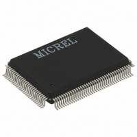
KSZ8841-PMQL Micrel Inc, KSZ8841-PMQL Datasheet - Page 3

KSZ8841-PMQL
Manufacturer Part Number
KSZ8841-PMQL
Description
Single Ethernet Port + 32-bit/33MHz PCI Interface( )
Manufacturer
Micrel Inc
Specifications of KSZ8841-PMQL
Controller Type
Ethernet Controller, MAC
Interface
Bus
Voltage - Supply
3.1 V ~ 3.5 V
Operating Temperature
0°C ~ 70°C
Mounting Type
Surface Mount
Package / Case
128-MQFP, 128-PQFP
Operating Supply Voltage (typ)
3.3V
Operating Temperature Classification
Industrial
Mounting
Surface Mount
Pin Count
128
Lead Free Status / RoHS Status
Lead free / RoHS Compliant
For Use With
576-1633 - BOARD EVALUATION KSZ8841-PMQL
Current - Supply
-
Lead Free Status / RoHS Status
Compliant, Lead free / RoHS Compliant
Other names
576-2117
KSZ8841-PMQL
KSZ8841-PMQL
Available stocks
Company
Part Number
Manufacturer
Quantity
Price
Part Number:
KSZ8841-PMQLI
Manufacturer:
MICREL/麦瑞
Quantity:
20 000
How to Set Wake-Up Frame
The KSZ8841-PMQL supports up to four Wake-Up Frames. Each Wake-Up Frame can be defined by the user. Initially,
the user needs to know the Wake-Up Frame pattern that they are planning to use. The user can mask or select first
64bytes of the Wake-Up Frame by Wake-Up Frame Mask Register. Each bit of the mask register corresponds to each
byte of the Wake-Up Frame. For example, bit 0 of the Wake-Up Frame 0 Mask 0 Register corresponds to the first byte of
Wake-Up Frame, bit 1 of the Wake-Up Frame 0 Mask 0 Register corresponds to the second byte of the Wake-Up Frame
and similarly, bit 63 of the Wake-Up Frame 3 Mask 3 Register corresponds to the 64th byte of the Wake-Up Frame (see
Table 1 for all bits of the Wake-Up Frame 0-3 Mask Register). When the mask register bits are set to 1, the device will
perform cyclic redundancy codes and calculate all the selected bytes for cyclic redundancy codes based upon the
Ethernet CRC-32 standard. After the device finishes the CRC calculations for a Wake-Up Frame, the result of the CRC
calculation is compared against the value of the 32-bit Wake-Up Frame 0-3 CRC 0-1 registers. If the calculation value is
same as the value of the corresponding Wake-Up Frame 0-3 CRC 0-1 registers, then the incoming frame is treated as the
Wake-Up Frame and the PMEN pin is asserted for remote control function. The user also needs to calculate the values of
the Wake-Up Frame in advance based on the known Wake-Up Frame pattern and then write the calculated CRC value to
the Wake-Up Frame 0-3 CRC 0-1 registers.
The following steps are required to place the KSZ8841-PMQL into Wake-Up Frame mode:
In the Wake-Up Frame mode, the device will calculate incoming frames based on the selected bytes of the Wake-Up
Frame 0-3 Mask 0-3 Register. If the frame has the same result with one of the 32-bit Wake-Up Frame 0-3 CRC 0-1
registers, then the frame is treated as a remote Wake-Up Frame and the PMEN pin is asserted for the remote control
purpose.
Involved Control Registers and bits are shown in Table 2.
The system can bring the device out of the Wake-Up Frame mode by resetting MPRXE bit [3-0] in WFCR register.
Micrel, Inc.
Register
CPMC
WFCR
May 2007
1. Set PME_Enable bit 8 in CPMC register.
2. Setup Wake-up Frame 0-3 Enable bit [0-3] in WFCR register to select how many wake-up frame will be supported
3. Setup 64bit Wake-Up Frame 0-3 Mask 0-3 registers based on the Wake-Up Frame pattern, set to '1' means the
4. The user can define the Wake-Up Frame pattern by them. For the Wake-Up Frame to be detected, the user
5. User also can find a software with source code from our software documents provided in the hardware.c
for the Wake-Up Frame mode.
byte to be selected, set to '0' means the byte to be masked.
needs to calculate all selected bytes of the Wake-Up Frame in advance for cyclic redundancy codes by Ethernet
CRC-32 standard and write the 32-bit CRC calculation result to the 32-bit Wake-Up Frame 0-3 CRC 0-1 registers
for the device identification the Wake-Up Frame. The user can select the first 64 Bytes of a Wake-Up Frame at
most.
\ether_CRC ( ) and then run the software program to calculate CRC result.
Bit
8
3
2
1
0
Name
PME_Enable
WF3E
WF2E
WF1E
WF0E
Table 2. Control Registers and Bits for Magic Packet Frame
Description
If this bit is set, the KSZ8841 can assert the PME_N pin. Otherwise, assertion
of the PME_N pin is disabled. This bit is cleared on power-up reset only and is
not modified by either hardware or software reset.
Wake up Frame 3 Enable
When set, it enables the wake up frame 3 pattern detection.
When reset, the wake up frame pattern detection is disabled.
Wake up Frame 2 Enable
When set, it enables the wake up frame 2 pattern detection.
When reset, the wake up frame pattern detection is disabled.
Wake up Frame 1 Enable
When set, it enables the wake up frame 1 pattern detection.
When reset, the wake up frame pattern detection is disabled.
Wake up Frame 0 Enable
When set, it enables the wake up frame 0 pattern detection.
When reset, the wake up frame pattern detection is disabled.
3
Application Note 142
M9999-050807-A
Default
0
0
0
0
0


