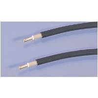
1986165-2 TE Connectivity, 1986165-2 Datasheet - Page 28

1986165-2
Manufacturer Part Number
1986165-2
Description
USE-2 SOLAR WIRE, 500FT, 12AWG, CU, BLK
Manufacturer
TE Connectivity
Type
Power Cabler
Datasheet
1.1-1579004-2.pdf
(36 pages)
Specifications of 1986165-2
Cable Length
500
Conductor Material
Tin Plated Copper
Cable Diameter
4.82mm
Wire Size
12AWG
Number Of Conductors
1
Color
Black
Cable Pitch (mm)
Not Required
Reel Length (imperial)
500ft
Reel Length (metric)
152.4m
Conductor Size Awg
12
Conductor Area Csa
3.31mm
Jacket Color
Black
External Diameter
4.826mm
Rohs Compliant
Yes
Color, Jacket
Black
Conductor Size
12 AWG
Insulation Material
Electron beam cross-linked Polyolefin
Material, Conductor
Stranded tin-plated copper
Standards
UL File E214122 and E314125, USE-2, RHH, RHW-2, XHH, XHHW-2 and Approved, VW-1 Flammability
Temperature, Operating
–40°C to +120°C
Voltage, Rating
1800/2600 VAC/VDC
Max Conductor Temperature
90° Wet or Dry
Voltage Rating
600 Volts (UL)
Product Type
Cable
Cable Type
RHH, RHW-2, XHHW and USE-2 Rated, UL 854 Approved
Wire Size (mm² [awg])
4.0² [12]
Rohs/elv Compliance
RoHS compliant, ELV compliant
Lead Free Solder Processes
Not relevant for lead free process
Rohs/elv Compliance History
Converted to comply with RoHS directive
Packaging Quantity
500 Ft. per Reel
Lead Free Status / RoHS Status
Compliant
3.2 Connector Latching
3.3 Disconnecting
26
SOLARLOK Interconnection System
Assembly and Installation Guidelines
When mating the SOLARLOK connectors, ensure the following:
■
■
■
Disconnect circuit from load before unplugging connectors.
Cable assemblies should be labeled using Tyco Electronics Label, Part No. 1394470-1.
Unmating of the connector
All specifications subject to change. Consult Tyco Electronics for latest specifications.
C A U T I O N : This connector must not be disconnected under load.
Connectors labeled with a plus or minus are keyed and can only be mated to similarly marked and
keyed connectors.
The polarity of the “neutral” connector must labeled with Part No. 1394725-1 or Part No. 1394725-2
nearby the connector.
The connector system is fully latched only when the latches are flush with the mating connector.
After the connector is fully latched, the optional latch locking clip may be snapped into place.
1 The locking mechanism is opened by depressing the latches.
2 Pull out the connectors. While depressing the latches,
C A U T I O N :
The “neutral” designated pin connectors incorporate no keying features and must
only be used for Serial Interconnection of Photovoltaic Modules.
The neutral product should not be used where maintaining polarity is critical.
disconnect the connector by pulling the connector halves apart.
2
1
1
(continued)
CAUTION: Do not disconnect the connector under load!
Catalog 889753-3
Fig. 7
(Female Connector)
Revised 6-2008
Fig. 8


