CY3280-MBR Cypress Semiconductor Corp, CY3280-MBR Datasheet - Page 7
CY3280-MBR
Manufacturer Part Number
CY3280-MBR
Description
BOARD EVAL CAPSENSE EXPRESS
Manufacturer
Cypress Semiconductor Corp
Series
CapSense® Express™ SmartSense™r
Specifications of CY3280-MBR
Design Resources
CY3280-MBR Schematic CY3280-MBR Bill of Materials CY3280-MBR Gerber Files CY3280-MBR Board Layout
Sensor Type
Touch, Capacitive
Sensing Range
4 Buttons/Keys
Voltage - Supply
3V
Embedded
No
Utilized Ic / Part
CY8CMBR2044
Operating Voltage
1.71 V to 3.6 V
Maximum Operating Temperature
+ 85 C
Minimum Operating Temperature
- 40 C
Operating Current
2.88 A
Silicon Core Number
CY8CMBR2044
Silicon Family Name
PSoC
Kit Contents
2x AAA Batteries, Axial Capacitors 10pF, 22pF, 33pF, 68pF, Quick Start Guide
Rohs Compliant
Yes
For Use With/related Products
CY8CMBR2044
Lead Free Status / RoHS Status
Lead free / RoHS Compliant
Interface
-
Sensitivity
-
Lead Free Status / Rohs Status
Lead free / RoHS Compliant
Other names
428-3083
Available stocks
Company
Part Number
Manufacturer
Quantity
Price
Company:

Part Number:
CY3280-MBR
Manufacturer:
Cypress Semiconductor Corp
Quantity:
135


CY3280-MBR CapSense Express with SmartSense Auto-Tuning Kit Guide, Doc. # 001-64772 Rev. **
2.
Demonstration Button
Kit Operation
CY3280-MBR kit is designed to demonstrate four CapSense buttons and a CapSense based power
button.
power button (POWER BUTTON). The kit is powered from two AAA on-board batteries, which are
placed below the kit in the battery holder. Configurable CapSense controller CY8CMBR2044
supports multiple features. The kit includes required hardware support to successfully demonstrate
each feature. See
CapSense controller using the kit.
The board has three connectors. Connector J5 can be used to demonstrate the SmartSense feature
and connectors J1 and J2 are used to provide external power to the kit and connect output signals
for CapSense controller to host systems.
Touch the power button first and ensure the power LED is turned on. Each CapSense button is
mapped to an LED (LED 0 to LED3) such that activation of each button can be verified visually by
monitoring the LED status. Active status of CapSense buttons are indicated by the ON status of the
LEDs.
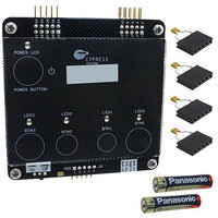
Figure 2-1. Top and Bottom Views of Kit
and Output LEDs
Power Button
Figure 2-1
Switch 2
(SW 2)
J5 Connector
illustrates these buttons: demonstration buttons (BTN0 to BTN3) and a CapSense
Kit Features chapter on page 13
Switch 1
(SW 1)
Battery Holder
to know how to demonstrate each feature of the
J1 Connector
J2 Connector
Potentiometer
Potentiometer
Delay
Sleep
7
Related parts for CY3280-MBR
Image
Part Number
Description
Manufacturer
Datasheet
Request
R

Part Number:
Description:
KIT UNIVERSAL CAPSENSE CTRLR
Manufacturer:
Cypress Semiconductor Corp
Datasheet:

Part Number:
Description:
CAPSENSE CONTROLLER DEV KIT
Manufacturer:
Cypress Semiconductor Corp
Datasheet:

Part Number:
Description:
MODULE LINEAR SLIDER CAPSENSE
Manufacturer:
Cypress Semiconductor Corp
Datasheet:

Part Number:
Description:
MODULE RADIAL SLIDER CAPSENSE
Manufacturer:
Cypress Semiconductor Corp
Datasheet:

Part Number:
Description:
MODULE SIMPLE BUTTON CAPSENSE
Manufacturer:
Cypress Semiconductor Corp
Datasheet:

Part Number:
Description:
MODULE MATRIXED BUTTON CAPSENSE
Manufacturer:
Cypress Semiconductor Corp
Datasheet:

Part Number:
Description:
MODULE BREADBOARD CAPSENSE
Manufacturer:
Cypress Semiconductor Corp
Datasheet:

Part Number:
Description:
BOARD DEV CAPSENSE CTLR
Manufacturer:
Cypress Semiconductor Corp
Part Number:
Description:
BOARD DEV CAPSENSE CTLR
Manufacturer:
Cypress Semiconductor Corp
Part Number:
Description:
KIT DEV CAPSENSE CTLR UNIV
Manufacturer:
Cypress Semiconductor Corp
Datasheet:

Part Number:
Description:
MODULE CAPSENSE PLUS
Manufacturer:
Cypress Semiconductor Corp
Datasheet:
Part Number:
Description:
SmartSense Evaluation Kit
Manufacturer:
Cypress Semiconductor Corp
Part Number:
Description:
Manufacturer:
Cypress Semiconductor Corp
Datasheet: