CY3280-MBR Cypress Semiconductor Corp, CY3280-MBR Datasheet - Page 9
CY3280-MBR
Manufacturer Part Number
CY3280-MBR
Description
BOARD EVAL CAPSENSE EXPRESS
Manufacturer
Cypress Semiconductor Corp
Series
CapSense® Express™ SmartSense™r
Specifications of CY3280-MBR
Design Resources
CY3280-MBR Schematic CY3280-MBR Bill of Materials CY3280-MBR Gerber Files CY3280-MBR Board Layout
Sensor Type
Touch, Capacitive
Sensing Range
4 Buttons/Keys
Voltage - Supply
3V
Embedded
No
Utilized Ic / Part
CY8CMBR2044
Operating Voltage
1.71 V to 3.6 V
Maximum Operating Temperature
+ 85 C
Minimum Operating Temperature
- 40 C
Operating Current
2.88 A
Silicon Core Number
CY8CMBR2044
Silicon Family Name
PSoC
Kit Contents
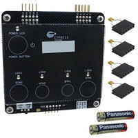
2x AAA Batteries, Axial Capacitors 10pF, 22pF, 33pF, 68pF, Quick Start Guide
Rohs Compliant
Yes
For Use With/related Products
CY8CMBR2044
Lead Free Status / RoHS Status
Lead free / RoHS Compliant
Interface
-
Sensitivity
-
Lead Free Status / Rohs Status
Lead free / RoHS Compliant
Other names
428-3083
Available stocks
Company
Part Number
Manufacturer
Quantity
Price
Company:

Part Number:
CY3280-MBR
Manufacturer:
Cypress Semiconductor Corp
Quantity:
135


2.3
CY3280-MBR CapSense Express with SmartSense Auto-Tuning Kit Guide, Doc. # 001-64772 Rev. **
The kit can be powered from three sources. This includes power from on-board battery and external
power through the J2 connector. A protection circuit is provided to prevent damage if both these
sources are connected at the same time. The protection circuit allows only one power supply to be
active at a time. The supply that has higher potential powers the kit. Therefore, to power the kit with
less than 3 V external power, the battery should be removed. To power the kit from the battery,
external power supply should not be connected or should not be higher than the battery voltage
(3 V).
The two power sources mentioned above are connected to a series pass switch, which is controlled
by the CapSense based power button. An LED is used to indicate the power ON condition of the kit.
The third power source option is through the J5 connector; this power supply does not have
protection circuit. It is recommended not to power the kit from any other source when the external
power through J5 is connected.
Four CapSense buttons and receptive LEDs are connected to the CapSense controller used for
demonstration. The output signals and hardware strapping inputs are also connected to J1 and J2
connectors. This helps to connect them to host and monitor status and control the CapSense con-
troller.
Controller Pin Assignment Details
The following table shows the pin assignment of the CapSense controller. To learn how to assign
pins for your design and recommendations on pin selection, refer the
Pin
10
11
12
13
14
15
16
1
2
3
4
5
6
7
8
9
GPO1
GPO0
Toggle/FSS
Delay
CS0
CS1
V
CS2
ARST
CS3
XRES
ScanRate/Sleep
V
GPO3
CMOD
GPO2
SS
DD
Label
GPO activated by CS1
GPO activated by CS0
Controls FSS and toggle features
Controls delay off time
CapSense input 0
CapSense input 1
Ground
CapSense input 2
Controls auto reset delay
CapSense input 3
Device reset, active high, with internal pull down
Controls scan rate and deep sleep
Power
GPO activated by CS3
External integrating capacitor, connect a 2.2 nF
(±5%) between this pin and ground
GPO activated by CS2
Description
CY8CMBR2044 data
Leave open
Leave open
Leave open
Leave open
Ground
Ground
Ground
Ground
Ground
Leave open
Ground
Leave open
Ground
Unused
Kit Operation
sheet.
9
Related parts for CY3280-MBR
Image
Part Number
Description
Manufacturer
Datasheet
Request
R

Part Number:
Description:
KIT UNIVERSAL CAPSENSE CTRLR
Manufacturer:
Cypress Semiconductor Corp
Datasheet:

Part Number:
Description:
CAPSENSE CONTROLLER DEV KIT
Manufacturer:
Cypress Semiconductor Corp
Datasheet:

Part Number:
Description:
MODULE LINEAR SLIDER CAPSENSE
Manufacturer:
Cypress Semiconductor Corp
Datasheet:

Part Number:
Description:
MODULE RADIAL SLIDER CAPSENSE
Manufacturer:
Cypress Semiconductor Corp
Datasheet:

Part Number:
Description:
MODULE SIMPLE BUTTON CAPSENSE
Manufacturer:
Cypress Semiconductor Corp
Datasheet:

Part Number:
Description:
MODULE MATRIXED BUTTON CAPSENSE
Manufacturer:
Cypress Semiconductor Corp
Datasheet:

Part Number:
Description:
MODULE BREADBOARD CAPSENSE
Manufacturer:
Cypress Semiconductor Corp
Datasheet:

Part Number:
Description:
BOARD DEV CAPSENSE CTLR
Manufacturer:
Cypress Semiconductor Corp
Part Number:
Description:
BOARD DEV CAPSENSE CTLR
Manufacturer:
Cypress Semiconductor Corp
Part Number:
Description:
KIT DEV CAPSENSE CTLR UNIV
Manufacturer:
Cypress Semiconductor Corp
Datasheet:

Part Number:
Description:
MODULE CAPSENSE PLUS
Manufacturer:
Cypress Semiconductor Corp
Datasheet:
Part Number:
Description:
SmartSense Evaluation Kit
Manufacturer:
Cypress Semiconductor Corp
Part Number:
Description:
Manufacturer:
Cypress Semiconductor Corp
Datasheet: